![You suck at protoshop. No, you [i]really[/i] oo.](http://blog.gg8.se/images/you-suck-at-photoshop-you-really-do-your-awful.png)


Testing Gameboy input voltage ranges
July 22nd, 2009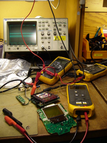
Introduction
Recently there was a discussion about on 8bc about a new way of backlighting DMG’s. Bonewire’s backlighting method replaces the batteries with two 9V batteries. This raised the discussion of whether you could power the Gameboy directly with a 9V battery, or whether it would explode/otherwise fail.
I wrote a post about the inner workings of the regulator and promised to come back with some more measurements of the performance of the regulator at different voltage levels.
To clear possible confusion: One important aspect of the regulator is that it’s a switching type regulator which is using a feedback mechanism to keep the voltage steady. Because of its design it’s able to do so whether the input voltage is lower or higher than the target voltage of about +5V. Thus, the input voltage may vary, while the output voltage stays (relatively) constant. This is useful for battery operation since the batteries can used as long as they are able to give enough current, whether or not their voltage is low. Switching power regulators, in general, also have a power conversion ratio: Little energy is lost in the conversion. (As opposed to a linear regulator, like the 7805 & co, which are guranteed to wate at least a certain amount of energy as heat)
Test Conditions
The goal of the test is to benchmark the input voltage range at which a Gameboy power supply would work at. The test subject was a DMG-CPU-7 revision motherboard with a DC CONV DMG converter. (There are at least two versions of the regulator board; the other one is marked DC CONV 2 DMG and has a couple more components on it.)
I used a xzakox type flash cartridge loaded with LSDj, playing a melody, with power save set to off.
Here a few notes on the measured values:
- Vin was adjusted in steps of 0.5 V and 1.0 V. The value is accurate to ±10 mV for all it matters
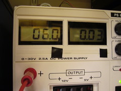
- Vout was measured with a multimeter and is accurate.
- Iin is the input current as displayed by the power supply unit, and is fairly inaccurate. (It only shows the general tendency)
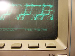
- DC/DC control RMS/f This value is also a bit hit and miss. I tried to read out the frequency which the DC/DC converter was working at, from the oscilloscope, to the best of my ability. This value fluctuated a lot, and is also just there to give a general picture of the freqeuncy. At the lower values the oscilloscope was unable to detect the frequency at all.
That is what the cryptic RMS voltage is there for. It should give a rough idea of the duty cycle of the control wave. - Notes These are my observations for some of the voltages.
Test Data
| Vin (V) | IIn (A) | Vout (V) | DC/DC control RMS/f | Notes |
| 1.5 | 0.15 | 4.79 | ~2.1V | Prone to crash, no sound, DC/DC buzz on startup |
| 2.0 | 0.12 | 4.82 | ~2.4V | No sound |
| 2.5 | 0.11 | 4.84 | ~2.7V | Display will lose data when playing sound |
| 3.0 | 0.05 | 4.87 | ~3.0V/~260kHz | Appears to work normally, possibly a bit glitchy/unstable |
| 3.5 | 0.06 | 4.86 | ~3.2V | |
| 4.0 | 0.05 | 4.87 | ~3.5V/~300kHz | Fully normal operation |
| 5.0 | 0.05 | 4.88 | ~3.5V/~320kHz | |
| 6.0 | 0.04 | 4.89 | ~3.6V/~390kHz | |
| 7.0 | 0.04 | 4.89 | ~3.6V/~415kHz | |
| 8.0 | 0.04 | 4.90 | ~3.6V/~460kHz | |
| 9.0 | 0.03 | 4.90 | ~3.7V/~500kHz | |
| 10.0 | 0.03 | 4.90 | ~3.7V/~510kHz | |
| 11.0 | 0.03 | 4.89 | ~3.0V/~700kHz?? | |
| 12.0 | 0.03 | 4.89 | ~2.6V/??? |
Observations and conclusions
Low voltage operation
The first interesting observation is the behavior in the low end of the voltage spectrum. The regulator could manage to keep the CPU alive at an input voltage as low as 1.5V. However, at that voltage there were significant power losses in the conversion, sound wouldn’t work and the Gameboy would crash easily.
At the transition 2.5V->3V you can see a significant change in input current, and I also noticed a change in behavior on the oscilloscope. I’d define 3V as the absolute minimum voltage that the regulator board can handle stable.
Sidenote: This possibly opens the door for using a Li-Ion battery for powering a DMG.
Normal voltage operation
At 4.0 V the Gameboy is definitely operating normally. As the input voltage is increased, the switching frequency is increased of the regulator is increased. No abnormal behavior. At no point during the testing did I notice and excessive heat production in the regulator circuit.
Above-normal voltage operation
4 AA batteries can not reasonably produce voltages higher than 7 V, so anything above that could be seen as outside the standard range of operation.
So what are the effects of voltages above 7 V? The regulator itself seems to handle it fairly well. And the +5V output only fluctuates 100 mV, so the CPU won’t be affected. However, while the +5V is regulated, the -18V line used by the LCD is not directly regulated, but instead current limited by a 510 Ohm resistor.
It is possible that the increased input voltage will also increase the LCD voltage in such a way that it damages the LCD. The Gameboy I used for testing already had a slightly damaged display, but when I was done wih the testing its display was more or less completely broken (would turn off or glitch out within seconds after turning on the power, regardless of input voltage)
I tried feeding my known good Gameboy with 9V for a few minutes, with a moderate contrast setting, without any problems. However, it’s possible that the extreme positions of the contrast dial will slowly destroy the LCD, when the input voltage is >7 V. If so, it could probably be fixed by changing the control voltage range for the contrast dial.
I’ll have to investigate that further, but my preliminary conclusion is that you can feed the Gameboy with a 9V battery without problems.
February 17th, 2013 at 1:32 pm
Any updates on the feasibility of 9v operation? I have a backlit ‘biverted’ DMG and am exploring the possibility of using 14500 lithium cells to in 2S2P (8.4v max, 7.4v nominal @1500-1800mAh) configuration. I also have a Gameboy pocket which has been successfully modified to run on 10440 cells in 2P configuration, which allows the use of a flashcart and backlight, power for which the MGB cannot sustain on a mere 2 AAA cells.
October 22nd, 2013 at 9:52 pm
[...] To power a Gameboy Classic (DMG) you usually use 4 AA batteries. Which are as you buy them, rechargeable or not. The other day I was searching and reading blog post about switching power supply module of the Gameboy Classic and found it to be pretty interesting. link [...]
August 17th, 2016 at 8:34 am
I got a pocket running rather swimmingly off of a direct 5V input. Your assessment of the LCD issue is correct, though - as the voltage increases, the output on the -18V pin grows increasingly more negative, and the output on the screen becomes darker.
September 29th, 2016 at 11:08 pm
I use LSDJ on a GB cartridge, and I’ve run a Gameboy Pocket (which usually uses 2xAAA) from a 5V cellphone charger without any problems whatsoever.
I’ve also used a single 3.7v AAA-sized Li-Ion in the PGB (and a blank AAA) with similar success. Whenever I use rechargeable 2xAAAs (NiMH), there isn’t enough power for the screen, and it dims during playback. This isn’t a problem for the Li-Ion, and it’s brilliant!