![You suck at protoshop. No, you [i]really[/i] oo.](http://blog.gg8.se/images/you-suck-at-photoshop-you-really-do-your-awful.png)


Pushpin Gameboy MIDI cable build report (Failed)
November 29th, 2007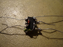
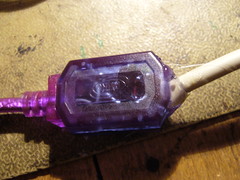
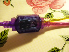
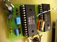
Lower right picture: Original junction box.
Summary: If you bought the components listed on my instruction page, you may want to wait a little for further instructions before you put it together. Some things may be wrong in that schemativ (Most probably resistor values.)
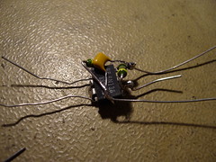
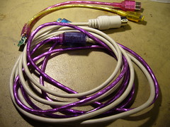
Time for a build report of my brand new Pushpin MIDI cable. First the positive things: I managed to build it as planned, and fit it into smoothly into the little plastic junctions box. The reason I did it this was because I was inspired by AlphA’s ninja style soldering.
It even went so smooth, and looked so nice that I was convinced that it would work right away. Unfortunately, no even close to the truth!
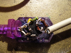
Pushpin didn’t react at all. After testing a lot of different things, I finally ripped the box open again. I had connected the MIDI cable the wrong way around. Damn. And the circuit, as you can see, is very compact, and was also glued to the box to keep it stable. I was forced to clean off the pins and connect the MIDI to the opto-coupler LED withut any additional components. Still didn’t work.
It was about at that time I started to work on a simple test program to indicate whether there is any traffic on the so called SD pin on the link port, which is what Pushpin is using to read MIDI data. The program can be downloaded here: SD Pin Monitor. However, when trying it out, my sound card suddenly stopped working. No$gmb froze when using sound, and most other programs returned an error. I have no clue why. A reboot helped, but it still delayed me a bit.
Still didn’t work. It was not until I connected the MIDI straight to link port that things started giving a hint of working. (MIDI Gnd <-> GB Gnd and MIDI signal <-> GB SD pin) Doing it that way, the test program started responding. Even Pushpin started playing a couple of random notes, although it was nothing of what I actually played, and it was a bit random, not every note returned a sound from PP.
So, here I am, with my cable interface destroyed, not knowing what the problem was. It’s annoying because there are several possible error sources, like:
- Badly timed output from my keyboard (A Radium49)
- Construction error in the adapter I built. (Short circuit or lose contacts)
- Wrong resistor values in my schematic may have blocked the signal somewhere across the way.
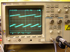
I will try to do a more scientific troubleshooting on my school’s lab, where I have access to oscilloscopes and prototype boards, to see if I can trace down the problem. So for now, if you’ve bought the components for the schematic I described before, you may want to wait a while for my results.
On the other hand, it would be cool if one or three people could build my circuit to see if it was just something I did wrong when I built mine. I don’t know. In not too long, we’ll know.
Nerd arts (The man, his blog and his arts)
November 28th, 2007I recently became an editor of nerdarts.com, a blog for nerdcore stuff. That’s what I do when I’m not blogging here. My most recent post there is a little rant about the two “Chip music is dead” compilations (archive.org) floating around the intarwebz. Instead of duplicating the post here, I’ll simply link to it.


Jeremiah is not only the creator of the nerdarts blog, but also a painter. He paints mostly on oil paintings, (<- Please correct me if I'm wrong about that) and many of his paintings have a video game or other pop cultural theme. Or Pop surrealism, as he puts it.
If I hade the money, I’d buy some of his paintings straight away. Yes, this is an official order from me, go and buy his art!
He has an art blog and a store on etsy, with the items currently for sale. Check it out.
One little OCD-ish thought is that I think that his art blog would be better off on the domain nerdarts.com and the blog currently on nerdarts.com would be better off on nerdkore.com.
Pushpin Gameboy MIDI synth now open source!
November 27th, 2007Have you ever heard about the Pushpin Gameboy MIDI synth? It’s a mysterious thing that I first saw maybe around 2000 or 2001. Over the years I’ve tried to reach the creators of this project, but without success. I thought the whole thing was fake, and that the music was perhaps made with LSDj or some other software.
As I know now, that’s not the case, but I wonder why it took them 7 years of silence before getting Pushpin out to the world.
This is an interesting piece of software that I have waited for for a long time now. I’ll build an interface as soon as I can. And I’m also going to try to do what I can to help the project, in terms of hardware and software development.
So far, I’ve written a Pushpin hardware tutorial, which I will update as time goes by.
The program and source code can be downloaded from the Pushpin Google Code page and there’s also documentation on variogr.am.
Gameboy på svenska
November 24th, 2007Jag råkade snubbla över ett svenskt Gameboy-forum, som också har ambitionen att vara en speldatabas, med recensioner. Jag vet inte hur bra de har lyckats hittills, men sidan verkar trevlig, och jag rekommenderar ett besök för dem som är intresserade.
(Tack Småm. Du hjälpte mig hitta sidan utan att ens veta om det. ![]() )
)
SID2SID with two different SID flavours: Finished
November 22nd, 2007I finally inished my special SID2SID, which has a little hack that allows you to use two different flavours of SID on the same board, at least if used on a 6581 board. The trick is to regulate the 12V used for the 6581 down to 9V, for the 8580. The 8580 should use the same filter caps as 8580 always uses. I don’t remember the value, but the SID2SID manual covers this.
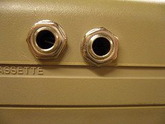
Here’s my test setup:
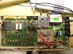
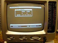
Prophet64 still identifies the main SID, a 6581. On the right, the audio outpus from the SIDs.
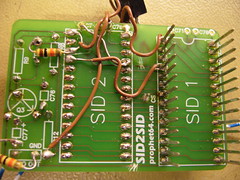
And here is a closer look of the little beauty. It’s too much of a snake’s nest, but that was because of a mistake of mine. The left picture is the bottom side of the SID2SID. It’s filled with dirty tricks. The first thing I want to point out is the voltage regulator. It has three wires. For the voltage regulator to have any effect at all, you have to cut the trace to VDD and connect the voltage regulator. (If you don’t know, or can’t find instructions, how to connect a voltage regulator, you probably shouldn’t do this mod, so I won’t tell you the exact wiring.)
I first cut the wrong trace, so there’s one excess wire to fix that.
The regulator should be a 7809, (+9 V regulator) but all I could find was a 7808. (+8 V regulator) That’s 1 V too low, but works, and will hopefully help keep the chip cool. The big cap attached to it was an attempt to keep noise in VDD to a minimum, but didn’t help much. However, it fits perfectly between the IC sockets and keeps the regulator steady in one place.
The resistor on the upper left grounds the SID sound input, which reduces the noise a little. The resistor on the lower left charges DC blocking cap, so that it’s nicely charged when you plug it into something. Hopefully this will help protect the chip, but maybe it will make it burn out faster. Time will tell.
No sounds samples up yet sorry, but it works fine. What doesn’t work fine is joystick port 2, where the fire button seems to be fried from ESD. (I finally realized this) So unless I learn how to use P64 without a mouse, no fun for some time. (But I can still use drummer and bassline of course.)
In the long run, I’d like to implement one or more of AlphA’s C64 mods. I will also try to modify the filter circuit in a strange way, bend if you will. Any news, and you’ll hear it here.
Also, fuckings to ps.
Update: Answer to Joey’s question:
In order to do what you want to you have drop the voltage and replace the caps, yes. The easiest way to replace the caps for SID 1 is to cut the 4 filter legs of the board, and solder 8580 compatible capacitors on the SID2SID board. The SID2SID cover this topic well.
As for regulating the voltage, I advise you to cut off the VDD pin, or possible bend it upwards in some acrobatic manner. That’s where the higher voltage goes onto the SID2SID board, somehow making sure that pin is not directly connect to the 12 V source on the board is crucial if you don’t want to fry two chips in one go. (*Shudders*)
Then you can connect the output of the regulator to that pin you’ve just bent/cut. Ground goes to ground and input goes to input. Crazy as I am, in your situation I would’ve tried to somehow fit the regulator where the VDD pin was. This way you can just put down the chip in the socket and the regulator leg would go in the right place. But that’s overkill, really.
Just make sure the VDD is regulated. And make sure the 12 V you have found is source is actually connected to the power supply. (Put your multimeter in diode mode, and probe the point you’ve found and pin 28 on the SID socket, while the machine is off)
If you need it, here is the SID pinout and the SID2SID manual.
Good luck!
Edit: The lurvtrut was removed in favour for an actual SID pinout.
Destroy your boot sector!
November 13th, 2007What do I and Dustin over at Virtual Roadside have in common? Let’s see, we’re geeky, we follow xkcd, and we luuuv messing around with boot sectors!
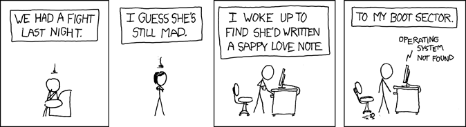
He made a nice snippet of ASM that resides in your MBR, which prints a little message of your choice. It’s inspired by this XKCD strip:
This takes me right back to when I was twelve or so and got Form.B from a floppy. I actually noticed it myself, and I checked it out with a program that could read flopppy disks on a low level. I don’t remember why I had such a program lying around, but I think it had something to do with my interest in DMF formatting, which allowed you to store 1.72 MB of data on a 1.44 MB floppy by (mis)using otherwise unused space. Anyway, the Form.B virus had a nice little message in it, greeting whoever managed to read it. I never felt that close to hardware until I started programming the Gameboy.
Where was I… Oh yeah, the MBR love letter. I tried it, and also filmed it and put on youtube, which you can watch below. I have the FreeBSD boot loader installed, which booted just fine. Maybe a computer with the MBR love letter is actually supposed to just boot afterwards, when using Windows’ boot loader, just that Dustin don’t want to say that out loud, so that less people will try it on their on computers? (No I haven’t checked the source code myself. It’s 6 AM and I’ve been up all night. Hopefully I’ll go to bed when I’ve finish this post.)
Now that the demo scene is producing size demos (Everything from 32 bytes up to 512 bytes) you could probably fit one of these into the boot sector to make this hack even nicer.
If you can’t read that blurry poem, it says:
Love me, love me not
My 'puter is all I got
With this malicious vector
Can I really restore my boot sector?
On a related note, recently the computer virus had its 25th anniversary. I’ve meant to say something about this, but I never got about doing it.
Edit:As Dustin points out the FBSD boot loader is only one boot sector big, which would be the reason why it works. Not only that, just by pressing any of the F keys associated with a partition, the boot loader automatically rewrites itself into the MBR. (The reason for this is to save the selection as the new default to the next next boot.)