![You suck at protoshop. No, you [i]really[/i] oo.](http://blog.gg8.se/images/you-suck-at-photoshop-you-really-do-your-awful.png)


nitro2k01’s SGB Enabler for EZ Flash Jr
August 19th, 2021EZ Flash Jr is an SD card based flash cartridge for the Gameboy and Gameboy Color. While economical, there’s one feature that has been missing from it, namely good support for SGB (Super Gameboy). You can sometimes get it to work by hitting the reset button at exactly the right time, but even then any SGB enabled game would lack any SGB enhancements, like custom borders. The SGB Enabler is a modified version of EZ Flash Jr Kernel 1.04e which mostly solves these problems.
This is a beta version - feedback appreciated. Especially from people using a NTSC SNES or a SGB2.
What was the problem and how does the SGB Enabler work?
The SGB contains a full Gameboy CPU and the SNES is used to show the graphics and sound from the Gameboy. But before the SNES allows an image to be shown, it needs a message from the Gameboy to validate the cartridge. Unfortunately, EZ Flash Jr holds the CPU in reset (basically locks it up) while it’s loading its own firmware. Because of this, the timing is thrown off. The SNES never gets the message and only shows a black screen forever.
But the Gameboy CPU is still running in the background. The SGB Enabler sends the same commands as the Gameboy boot ROM would normally send, and the SNES allows an an image to be shown.
How do you use the SGB Enabler?
Simply copy the included ezgb.dat file to the root of the SD card, overwriting the existing file. Then start the Super Gameboy. (download link at the bottom of the page.) You do not need to touch the reset button on either the cartridge or SNES. It just works.
Does the SGB Enabler restore all SGB functions?
Yes, it enables the game to use colorization and border graphics, and even special sound effects in the few games that use those. And Space Invaders 94’s SNES arcade mode works as well.
Is the SGB Enabler safe to use?
Yes. The SGB Enabler only modifies the kernel (menu), and doesn’t touch the firmware (FPGA). Therefore, you can simply restore it to its original state by copying the original ezgb.dat file from EZ Flash Team onto the SD card, and there’s no risk of bricking. You do not need to upgrade to FW5 (which Team EZ Flash removed). It’s recommended to use FW4.
Can I still use the SGB Enabler on a DMG/GBC?
Yes, the only downside is that the boot time is longer because it always tries to send the commands to wake up the SGB as explained above. I will try to figure out a way to fix this later, but this is just an early beta version to get feedback from users. If this is a problem, simply replace ezgb.dat with the original file from EZ Flash. (Detecting the hardware is not as straightforward as it seems because the EZ Flash Jr has an internal boot ROM that erases the initial registers that programmers normally use to detect which type of hardware the game is running on.)
Does the SGB Enabler work on both PAL and NTSC Super Gameboys?
I only have a PAL SNES, but I’ve region modded it so I can select PAL or NTSC. In my testing, I’ve made sure the SGB Enabler works in both PAL and NTSC mode, but feedback from someone who has a real NTSC SGB would be appreciated.
The SNES reset button doesn’t work!
Please use the reset button on the cartridge, or power cycle the SNES to restart.
Download
LittleFM 0.5.2 released
November 21st, 2016LittleFM 0.5.2 is a bug fix release which fixes a bug where some files would incorrectly fail to load with the message “no blockjump”.
Pushpin modded for Arduinoboy/nanoloop MIDI
November 14th, 2016Get it here.
Pushpin modded for Arduinoboy/nanoloop MIDI

===========================================

This is a version of Pushpin which has been modded to use the regular link port

protocol instead of Pushpin’s original hack of reading MIDI UART directly on a

digital IO pin on the GBC link port. This version works with Arduinoboy in mGB

mode or the nanoloop MIDI adapter in MIDI mode. This version no longer works

with Pushpin’s original MIDI UART mode.
It has been modified to be able to run on non-GBC Gameboys, since Pushpin hangs
when it tries to switch to GBC double speed mode. The display is slightly
glitched on monochrome Gameboy but otherwise it should work fine.
This version works just like the original. Press up/down to select MIDI channel
assignment, then press start to begin receiving MIDI. Refer to Pushpin’s manual
for advanced usage and MIDI CC assignment.
Since I don’t have a GBDK environment set up, it was easier for me to do this
by modifying the ROM using BGB. For this reason there’s currently no source
code. I should probably make a proper release source code at some point. Such
a version could offer a mode selection at boot time to allow either MIDI UART
mode or SPI mode.
nitro2k01 - 2016-11-14
http://blog.gg8.se/wordpress/
Pushpin documentation and source code:
https://github.com/bwhitman/pushpin
eBay error: “The seller has disallowed combined payments and shipping discounts.”
July 14th, 2016I recently scored a few auctions from an eBay seller who promised combined shipping. Upon requesting a new quote to reflect the combined shipping fee, I got the following error:
“The seller has disallowed combined payments and postage discounts. Please proceed to checkout to complete your purchase.” (Error code 80016)
When researching it, some people pointed out that it’s up to the seller whether they want to allow combined shipping. This was irrelevant in my case since the seller clearly stated in the description that they support combined shipping. Someone even suggested that a seller could lie, and that you would need to contact the seller in advance to get a written confirmation before bidding. However, I’m skeptical that it would be permitted by eBay’s rules to lie about something like that in the item description. Other results were not helpful either,
At last I figured out the probably cause the issue. For whatever reason, I was logged in to ebay.co.uk. When I instead tried logging in at ebay.com I could request a new quote. In my case, they got back within minutes of receiving the request, with a new price.
You learn something new everyday
April 8th, 2015The other day, for whatever reason, I wanted to know how fast the Nintendo logo scrolls down the screen on a DMG. The boot ROM has been dumped since forever and this is a simple matter to investigate in BGB. In BGB select Gameboy as the system type in the system tab, check “bootroms enabled”, and click ok. Then reset the CPU. Now, assuming the boot ROM is in the specified location, you can debug it.
I added a breakpoint (debug, breakpoints) with condition (FF44)=90. This breakpoint triggers on every VBlank, ie when register FF44, LY, the LCD line counter, reaches value $90. This is a more certain way of triggering on VBlank than the interrupt vector for cases when the regular interrupt may not be triggered in time due to interrupts being disabled, or (as in this case) when the code doesn’t use interrupts at all.
By pressing F9 repeatedly and seeing how much the logo would move every time, it seemed that the logo moved 1 pixel every 2 frames. Or not. It actually alternates between waiting 2 and 3 frames between every progression. The code responsible for this is the following, at position $0060 in the boot ROM:
  00:0060 ld   e,$02
  00:0062 ld   c,$0C
  00:0064 ldh  a,[$FF44]
  00:0066 cp   a,$90
  00:0068 jr   nz,$0064
  00:006A dec  c
  00:006B jr   nz,$0064
  00:006D dec  e
  00:006E jr   nz,$0062
This is the wait for VBlank routine. We have three layers of loops here. Outermost, we have a countdown using the E register, to wait for two frames. The innermost loop (0064-0068) wait until LY=$90, which just like with the breakpoint above signifies the start of the VBlank period. Both straightforward mechanisms.
The interesting part is the dec c/jr nz,$0064 mechanism. On the surface, it seems to be added to prevent the outer loop from exiting too early. On the second iteration of the outer loop, LY would still be $90, and the loop would immediately fall through instead of waiting for another frame. The C loop iterates 12 ($C) times, but interestingly jumps through the inner loop as well. This means that LY may or may not stop being $90 before the middle loop ends, depending on the exact time that the loop is entered. In other words, sometimes the code gets stuck in the inner loop for an extra frame when C=1, and then the last dec C is executed, and the outer loop exits.
The animation jitters between 2 and 3 frames consumed between each pixel move, so the animation takes 25% longer time than a naïve reading of the code would suggest. (5 frames per 2 pixels vs 4 frames per 2 pixels.) Now the question is if this was intentional to make the animation go slightly slower, or just a bug. If it was just a bug, it would have been easy to fix by making the dec C loop jump back to 006A (the dec C instruction) and setting a higher initial value for C.
Bug or intentional slowdown of the animation? Would be interesting to know.
Gradual Decline - A quick Gameboy glitch ROM
December 17th, 2014Gradual Decline - A quick Gameboy glitch ROM by nitro2k01
=========================================================
This ROM explores the idea of what would happen if you wrote random data to
random IO registers and random positions in video RAM. If you like audiovisual
glitches, this is for you. The ROM generates randomized graphics, and bleeps,
bloops and static. Sometimes it will even produce tones that are vaguely
melodic, even if dissonant.
How to use
==========
Burn to a flash cartridge and run. It’s a unique experience each time you run
it. Even though this will not perceivably change the output of the ROM, you
may press buttons to seed external entropy into the random number generator.
https://blog.gg8.se
2014-12-17
Video:
Dumping the boot ROM of the Gameboy clone Game Fighter
December 9th, 2014
Game Fighter posts:
- Teardown
- Dumping the boot ROM
Inside every Gameboy there’s a small boot ROM, which scrolls the Nintendo logo down from the top of the screen, and plays the iconic po-ling sound. This 256 byte boot ROM also checks that said Nintendo logo is present in the ROM chip of the cartridge, and validates the checksum of the header. Up until the 1992 legal case Sega v. Accolade it was believed that this check gave Nintendo the legal authority to control which games were allowed to run on the console, as the “Nintendo” logo was copyrighted by Nintendo, but the the ruling gave a strong precedent that using this small piece of copyrighted data to achieve interoperability was allowable.
The boot ROM locks itself out from being read before leaving control of the CPU to the program running on the cartridge, maybe more due to necessity than preventing read-out of the ROM, since the bottom memory area near the CPU entry point also covers the interrupt vectors, which the game needs access to. But as a result, this boot ROM remained an elusive secret, which was assumed would never see the light of day.
It was not until 2003 that Neviksti extracted this ROM from a DMG, decapping the CPU chip, looking at the CPU die with a scanning electron microscope and painstakingly reading out the bits visually, all 2048 (8*256) of them.
In 2009, costis extracted the SGB boot ROM by externally overclocking the CPU right at the time when the boot ROM shuts itself out, which causes the write to the lock-out register to be ignored, and then it could be copied to the outside world. The GBC boot ROM was also dumped this way by costis soon after.

Just this year (2014) BennVenn made the process child’s play with a silly but effective method. All you need to perform the attack is a piece of wire! You solder one end of the wire to one of the crystal oscillation circuit, and scrape the other end of the wire against any grounded surface in the Gameboy, such as copper shielding plate. This causes the CPU to glitch to jump to a random location. If you’re lucky, this allows you take control of the code execution and, again, dump the boot ROM.

But, what about pirate Gameboy clones? For example this Game Fighter, which is a horizontal Gameboy clone. Also see my detailed teardown and analysis of this beauty. It also has a boot ROM, though slightly different in function. The Game Fighter, instead of scrolling the logo down the screen, starts the game immediately. I also knew from before that it checked that the logo was correct, but not the game’s ROM header checksum.

So I wrote a small program, did the glitching procedure and voila! I had the boot ROM. You can download it here:
Game Fighter boot ROM download
If you really wanted, you could use this ROM with BGB and for example single step through it in BGB’s debugger. To do this, go into BGB’s settings, go to the system tab, then check the bootroms enabled option, and point the DMG boot ROM field to the ROM file.
Since the Game Fighter boots immediately, unlike an original ‘boy, I made the ROM have an invalid logo in its header so it would lock up and give me time to try to glitch the execution. The procedure was the same as on an original Gameboy: Find the one the pins of the crystal driver that is the input, solder a wire to it, (pictured above) and brush the other side to a part of the board that is ground. For the Game Fighter, I found that I had better luck getting it to work if I first shorted it to ground (for example the negative battery terminal) on power on, then brushing it against the surface as I let it go.
I will post the program I used for dumping the boot ROM later, along with a more detailed description of how it works.
Here’s the boot ROM disassembled, which holds an interesting secret! (Disassembly of the original DMG boot ROM for comparison.)
        ld   sp,$FFFE           ;  0000  Set up the stack pointer.

        ; Clear VRAM.
        xor  a                  ;  0003
        ld   hl,$9FFF           ;  0004
Addr_0007:
        ldd  [hl],a             ;  0007
        bit  7,h                ;  0008
        jr   nz,Addr_0007       ;  000A

        ; Set up sound.
        ld   hl,$FF26           ;  000C
        ld   c,$11              ;  000F
        ld   a,$80              ;  0011
        ldd  [hl],a             ;  0013  [$FF26] = $80 Turn on sound

        ld   [$ff00+c],a        ;  0014  [$FF11] = $80 Channel 1 wave duty
        inc  c                  ;  0015
        ld   a,$F3              ;  0016
        ld   [$ff00+c],a        ;  0018  [$FF12] = $F3 Channel 1 envelope
        ldd  [hl],a             ;  0019  [$FF25] = $F3 Channel routing
        inc  c                  ;  001A
        ld   a,$C1              ;  001B
        ld   [$ff00+c],a        ;  001D  [$FF13] = $C1 Channel 1 low frequency byte
        ld   a,$77              ;  001E
        ld   [hl],a             ;  0020  [$FF24] = $77 Master volume

        ; Set up graphics.
        ld   a,$FC              ;  0021
        ldh  [$FF47],a          ;  0023  [$FF47] = $FC BG palette
        ld   a,$91              ;  0025
        ldh  [$FF40],a          ;  0027  [$FF40] = $91 Turn on LCD

        ; Compare the second half of the logo in the header against
        ; the second half of the Nintendo logo stored in the boot ROM.
        ld   de,Addr_0043       ;  0029
        call Addr_0073          ;  002C
        cp   a,$34              ;  002F  Will return $34 if successful.
        jr   nz,Addr_0036       ;  0031  If not, jump to a second compare operation.
        jp   Addr_00FC          ;  0033

        ; Compare the second half of the logo in the header against
        ; the second half of the mystery logo stored in the boot ROM.
Addr_0036:
        ld   de,Addr_005B       ;  0036
        call Addr_0073          ;  0039
        cp   a,$34              ;  003C  Will return $34 if successful.
Addr_003E:
        jr   nz,Addr_003E       ;  003E  If not, get stuck in an endless loop.
        jp   Addr_00FC          ;  0040

        ; Second half of the Nintendo logo, $18 bytes
Addr_0043:
        db   $DC, $CC, $6E, $E6, $DD, $DD, $D9, $99
        db   $BB, $BB, $67, $63, $6E, $0E, $EC, $CC
        db   $DD, $DC, $99, $9F, $BB, $B9, $33, $3E

        ; Second half of mysterious RIS or KIS logo, $18 bytes
Addr_005B:
        db   $00, $00, $00, $00, $76, $66, $C6, $31
        db   $00, $19, $66, $FF, $01, $88, $38, $C7
        db   $C6, $C8, $00, $00, $00, $00, $00, $00

        ; Subroutine: Compare the cartridge header’s logo against
        ; a given memory location
Addr_0073:
        ld   hl,$011C           ;  0073  Start comparing halfway into the logo
Addr_0076:
        ld   a,[de]             ;  0076
        inc  de                 ;  0077
        cp   [hl]               ;  0078
        jr   nz,Addr_0082       ;  0079
        inc  hl                 ;  007B
        ld   a,l                ;  007C
        cp   a,$34              ;  007D  $xx34 = The first byte after the header logo
        jr   nz,Addr_0076       ;  007F
        ret                     ;  0081
Addr_0082:
        ld   a,$85              ;  0082  Compare failed!
        ret                     ;  0084

        ; $77 filler bytes
Addr_0085:
        db   $ff, $ff, $ff, $ff, $ff, $ff, $ff, $ff
        db   $ff, $ff, $ff, $ff, $ff, $ff, $ff, $ff
        db   $ff, $ff, $ff, $ff, $ff, $ff, $ff, $ff
        db   $ff, $ff, $ff, $ff, $ff, $ff, $ff, $ff
        db   $ff, $ff, $ff, $ff, $ff, $ff, $ff, $ff
        db   $ff, $ff, $ff, $ff, $ff, $ff, $ff, $ff
        db   $ff, $ff, $ff, $ff, $ff, $ff, $ff, $ff
        db   $ff, $ff, $ff, $ff, $ff, $ff, $ff, $ff
        db   $ff, $ff, $ff, $ff, $ff, $ff, $ff, $ff
        db   $ff, $ff, $ff, $ff, $ff, $ff, $ff, $ff
        db   $ff, $ff, $ff, $ff, $ff, $ff, $ff, $ff
        db   $ff, $ff, $ff, $ff, $ff, $ff, $ff, $ff
        db   $ff, $ff, $ff, $ff, $ff, $ff, $ff, $ff
        db   $ff, $ff, $ff, $ff, $ff, $ff, $ff, $ff
        db   $ff, $ff, $ff, $ff, $ff, $ff, $ff

        ; Disable the boot ROM and hand over control to the game cartridge.
Addr_00FC:
        ld   a,$01              ;  00FC Write to the ROM disable register
        ldh  [$FF50],a          ;  00FE
It’s mostly like a stripped down version of the original Nintendo bootstrap. It turns on the sound circuit even though it does not play any sound. Perhaps this is for compatibility with some game that expects it to be turned on on start-up. The boot ROM also clears the video RAM, sets the background palette and finally turns on the LCD circuit.
The boot ROM interestingly enough only stores a reference copy of the second half of the Nintendo logo, even though there’s plenty of unused space. So the first half of the logo could be incorrect and the program would still start. Incidentally, Gameboy Color has a similar bug where only the first half of the logo is checked, which has prompted some pirate publishers to get creative and make logo combinations like HotKid, Niutoude and Yiutoudz using the bottom half of the logo that they can control freely. Read more on Neofuji. It wouldn’t matter in this case anyway, as the logo isn’t shown on the screen, only checked.

But what’s weirder is what the boot ROM does if the Nintendo logo check fails. It then does a second check, against an alternative logo that perhaps says KIS or RIS, simulated to the right for illustrative purposes. Again, the boot ROM only stores half the logo in this case as well, so there’s no way of getting the full logo without finding a matching game that contains the full logo in it header.
It may be checking specifically for a certain game by the same publisher. But why would the game have an alternative logo, when this logo is not shown on the Game Fighter, and would hang a genuine Gameboy? The only logical conclusion I can come to is that the game that this check was made for does a logo swap. Some examples of logo swaps (apart form the half logo hacks) can be found in the Neofuji post linked above. A logo swap works by switching in memory containing your own logo when the boot ROM copies the logo the into VRAM, and then switching back to the real logo when the check is done. This would normally fail on the Game Fighter, since it checks the logo much earlier than a real Gameboy.
But in the end, we may never know. If you have any clue which pirate publisher KIS/RIS/??? is please let me know!
Thanks to BennVenn for coming up with this method of accessing the boot ROM!
Where the donk does mGB store its channel 3 waveforms?
June 30th, 2014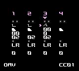
mGB, trash80’s Gameboy MIDI synth for use with Arduinoboy has support for selecting various waveforms for use with channel 3. If you look at the data loaded into wave RAM and search for it in the ROM you find nothing. Is the data generated algorithmically, perhaps? Let’s look into it.
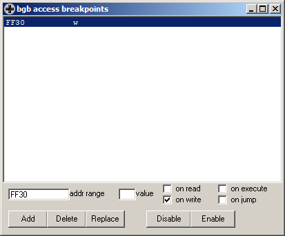
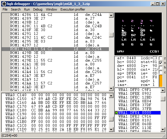
I may actually have the mGB source code lying around somewhere, but this is easy to figure out using BGB. First add an access breakpoint (debug, access breakpoints) to FF30 (the lowest address in the channel 3 wave buffer) and hit run. If mGB was already started, change the waveform or reset the CPU to make the write happen again.

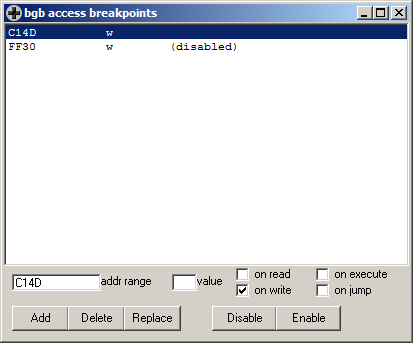
If you read the code, it seems like the waveform index is loaded from somewhere, and is then added to C14D, an address in RAM. If you go to that address in the data panel in the bottom of the window you can confirm that there are indeed waveforms there. Let’s place a write breakpoint to the address in RAM, maybe disable the old one, and rinse and repeat.
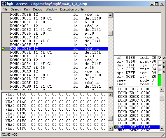
The code that creates the waveforms in RAM consists of a long row of instructions on the form
ld  de,C14D
ld  a,01
ld  (de),a
ld  de,C14E
ld  a,23
ld  (de),a
This is likely the GBDK C compiler’s output from something like…
waveforms[0]=0×01;
waveforms[1]=0×23;
…and so on. Or this may just be an example of the compiler doing something really stupid when you define a const array. The performance and size of such code compared to an optimized alternative is not exactly flattering, but that doesn’t matter much in this case.
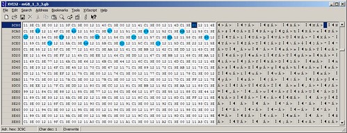
In other words, the actual data starts at address 3C9C and is spaced out so every 6th byte is waveform data. Above, the bytes for 0th waveform (starting at the hex editor’s cursor) are marked in a light, not-quite-cyan, blue. Click for a bigger image.
Can we do it better? Let’s try to patch the ROM to store the data in a linear fashion and then copy it into the position in RAM where it is later used. Or even better – as the wave data is not likely to be modified after the being copied into RAM – make the program read them directly from ROM instead of from RAM.
First start mGB and grab the wave data from RAM, for use later. First a back of the envelope calculation: there are 16 waveforms, each of size 16 bytes, leading to a total of 256 bytes. When mGB is at the main screen, select file, memory dump in the debugger. Choose a place to save the dumped file. We know from above that the data is stored starting at C14D, so enter that as the starting address. As size, enter 100, hex for 256.
Then go to 3C98 in the disassembly, which is the first instruction of the row of instructions that are used to fill up the wave data in RAM. The similar instructions before that one are used to initialize other memory. Don’t touch those.
We know form above that there are 256 bytes of wave data. We also know that it takes 6 bytes worth of instructions to copy one byte to memory. This means we can now calculate the end of this code area, or rather, the first address containing other code as 3C98+(100*6)=4298 (all hex, mind you!) You can now go to this address in the disassembly to confirm it’s correct. Press ctrl+G and enter 4298.
The group before that position reads
ld  de,C24C
ld  a,03
ld  (de),a
C24C is 255 bytes after C14D, and the next byte being written to, C254, is non-consecutive. This means 4298 seems like the correct address to jump to.
Now go back to 3C98 and create a jump to 4298. You can do this by simply placing the cursor at the correct place and starting to type jp 4298. When you type the first character, an assembler winow pops up to let you continue writing the instruction. Pressing enter or clicking ok will assemble the opcode. If all goes well you will now see it in the disassembly.


So, now to plan for where to put the 256 (100 hex) block of data. The area 3C9B-4297 is now “dead”, consisting of code that will never be executed. We could now place the data directly at 3C9B and 100 (hex) bytes forward. Or we could make our lives easier when editing and put the data at something easy to remember 4000 and 100 (hex) bytes forward. Any area that fits within the now dead memory area is ok, which is true for 4000-40FF.
Now press ctrl+G and go to 28B3, which is the place where the base address for the waveform lookup is loaded into the HL register. Start typing ld hl,4000 and press enter.

Time to save the file. Normally I would recommend to do file, fix checksums at this point, but since the file will be further edited, the checksum will change later anyway. So select file, save ROM as and save the file, preferably under a new name. Use whatever method your hex editor provides (or doesn’t provide) to overwrite 100 (hex) bytes from 4000-40FF. In my trusty ol’ xvi32, I had to first delete 100 bytes, then select file, insert and select the file previously saved containing the waveforms.
You can select an address to go to by pressing ctrl+G. You can select characters by selecting edit, select
A better hex editor may have a better method of overwriting an area with data form another file.


Confirm that the newly inserted waveform data is located at 4000 and not anywhere else. Press ctrl+page down to go to the last address. Confirm that the file is the right size by checking that the last address is FFFF or 65535 (depending on whether you are on the hex or character side of the display.) Save.
Load in BGB and confirm that the ROM doesn’t crash. To get the right warm fuzzy feeling inside, select file, fix checksums and then file, save ROM as, again.
For your convenience, you can download the modified ROM here.
Furrtek’s Airaki: quick game review and ROM dump download
May 14th, 2014
I’ve got mail! What’s inside? A cartridge of Furrtek’s second, and so far, latest game Airaki. The envelope (as well as the title field in the ROM header) is marked with the number 1, suggesting I’m receiving the first cartridge of this batch. The cartridge comes in a resealable “drug bag”, and there’s also an instruction sheet explaining the game mechanics.

The game comes in a generic “game” shell, a type often used by pirates. The cartridge has a label with our muscular furry hero holding his massive sword in an erect position. *cough*
Read on…
Dell PSU third pin fix
April 25th, 2014A few years ago, I bought a PSU for my Dell D600 on eBay which turned out to be a really crappy Chinese pirate PSU which suffered badly from interference. When I wanted to fix the interference by connecting the plug to a different, and genuine Dell PSU, I stumbled upon a problem. All modern Dell PSU’s have a ID feature to confirm that the PSU is genuine, using a 3rd pin center pin connected to an EEPROM. If this chip does not match, the laptop won’t allow the battery to be charged. While a less scrupulous 3rd party manufacturer can nag one of those ID chips from a broken genuine Dell PSU and pass the test with a any poor quality PSU, I had to transplant this ID chip somehow, to make the PSU work.


I recently got another Dell laptop with a broken PSU, which I could have if I could fix the PSU. Like last time, I decided to splice the cable with a board containing the chip.

This board was made from veroboard, and ws a bit bulky, so I decided to design and order a new one. This posted is an illustrated guide to how this board is used.

Gameboy Genius is proudly powered by
WordPress,
theme XodaFields by Mattias Wirf on XODA
Entries (RSS)
and Comments (RSS).
Jimmy Neutron is proud not to be a sponsor of this page!
This page was previously hosted on http://gameboygenius.8bitcollective.com/wordpress/ (*).
The gameboygenius subdomain was removed by Jose Torres (BleepBloop) 3/20-2010. RIP!
(*) This is an automatically generated link. Obviously, some pages were created after the move and didn't exist at the original URL written...