![You suck at protoshop. No, you [i]really[/i] oo.](http://blog.gg8.se/images/you-suck-at-photoshop-you-really-do-your-awful.png)


New track: Nitrojazz
January 26th, 2010Time for some NES-eque and short but sweet Gameboy jazz. Listen at chipmusic.org.
Sparkfun Free Day
January 8th, 2010


For those of you who missed it, yesterday was Sparkfun free day, when Sparkfun would give away $100 to all customers, up to a grand total of $100,000. I didn’t really expect to be one of the winners in the noble battle. As one might imagine the demand for the offer was high, and I expected that the pot would be used up within minutes. The problem however turned out to be quite the opposite. The server was so overloaded that nobody could get through. When submitting a form, the page would load for 5 minutes just to tell me the connection was aborted. I heard a rumour that someone had managed to place the first order order after 30 minutes. So I kept pressing F5 persistently as soon as a page returned an error, and I managed to place my order just in time. At that point things were working relatively well, given the circumstances, (Only had to refresh three times before getting a connection) And as you can see from the remaining time and money counters, $9000 (~90 users) were served over the course of three minutes. I’m guessing people started to give up by then.
My persistence paid off, and unless they mess up the shipping somehow, I’ll soon be the owner of a Spartan 3E FPGA.
How to patch your DMG to use a biverted palette
November 23rd, 2009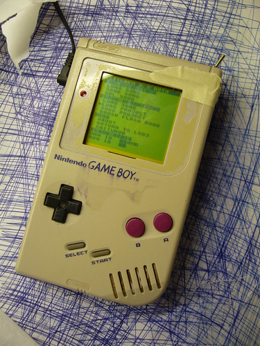
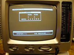
Inverted:
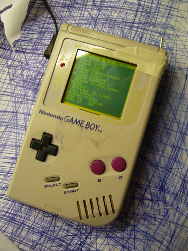
(Please excuse the shabby look, but that is my guinea pig Gameboy that I use for experimentation.)
I’ve already explained how you can invert the monochrome palette in LSDj which is useful if you have a DMG backlight with an inverted polarizer film on your DMG. But what if you want to use a normal palette for other software or games?
Modding the ROM of the game or program you want to invert the palette for is an option, but it may not be practical. Fear not however, the protocol that the DMG is using to transfer data from its all-in-one chip to the LCD is strikingly simple, and can easily be inverted with a 74hc logic circuit of your choice, a so-called biversion.
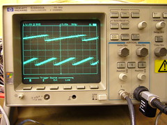
First let’s have a look at how the protocol works.
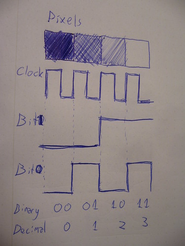
For the sake of this tutorial there are three important pins to keep track of. Data bit 0, data bit 1 and clock. At every rising edge clock edge (when the clock line changes from 0V to +5V) the current state of the data lines is recorded, and the corresponding pixel value is drawn to the currently active pixel on the LCD. This keeps goes until the whole screen is filled with an image. And then again and again. (Ok, there are more aspects to it, like so called “blanking” but that’s not relevant for this discussion)
So what you need to do is change the values of the data lines in such a way that black becomes white, light gray becomes dark gray and so on. The way to do this is by simply inverting the two data bits. There are (at least) two possible ways to do this.
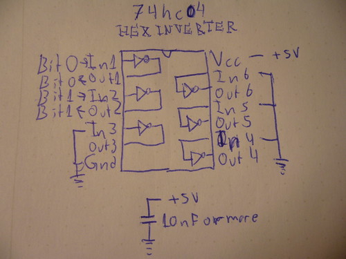
One way is to use a simple inverter like 74hc04, where you connect the data bits to the appropriate input and outputs. Also note two things abut the schematic:
1) I have connected all unused input to ground. (Unused outputs should remain unconnected)
2) I’ve added a bypass capacitor between Gnd and +5V
Neither one of these things are strictly necessary but they are good practice, and may help reduce interference to the signal if that would be a problem.
And obviously you can use any pair of inputs and outputs on the chip.
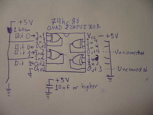
The other way of doing it, which is what I did for my prototype, is to use xor gates. (74hc86) The advantage of that method is that you can switch between the modes easily with a switch. If you xor a bit value with 0, you get back the same bit value. If you instead xor the bit value with 1, you get back the inverted value. So in this configuration, I’ve connected a weak pullup resistor, which sets one of the inputs to 1 by default, meaning the image is inverted by default. However, if those inputs are shorted to ground, the xor operation returns the original data and the picture is again unaffected.
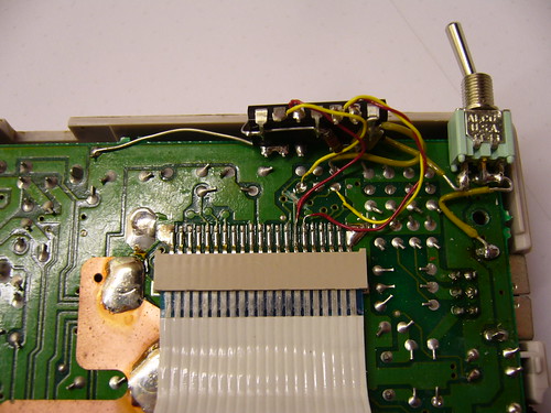
So, how does one actually connect the inverter? You need to cut the copper trace where the data and solder the input and outputs on each side of the cut.
This is what my prototype circuit looks like. I’ve connected the inputs of the inverter to the appropriate holes that are already available in the motherboard, but filled with solder.
A sidenote on these holes: They were most probably placed there to enable connection to the WideBoy unit, which was an official Nintendo development kit that allowed the screen image of a Gameboy to be displayed on a TV with the help of a NES.
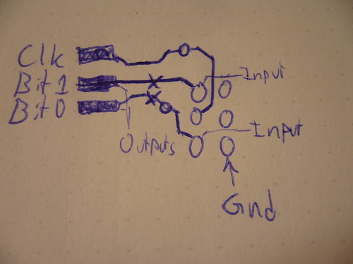
At any rate they come in handy now. The above diagram show you where to tap the input signals, where to cut the traces, and where to solder the output wires. When cutting the traces make sure you cut them properly, or you’ll have a conflict. Do not cut the Clk trace.
All three holes shown to the right in the diagram are connected to Gnd.
Last but not least, a video of the thing in action:
So… Tell me what you think. Is this information useful? Anything unclear? Is my English to quirky and corny? Anyone interested in buying kits for this thing?
The terms “biversion” and “bivert” were later coined for this mod by Bibin.
GBC Prosound idea
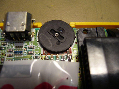
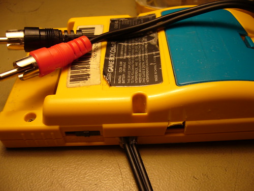
September 13th, 2009Sorry for the blog hiatus during and after my vacation. Before the vacation I came up with a new way of routing the audio cable that I don’t think I’ve seen before. (Feel free to correct me.) Most GBC prosound mods I’ve seen are based in the idea of routing the cable downwards to the bottom of the board.
My idea on the other hand is based on connecting the audio wires to the potentiometer as usual, then routing the cable over the PCB, so that it sits below the cartridge when the GBC is reassembled. The cable would then exit through a hole on the right side of the of unit.
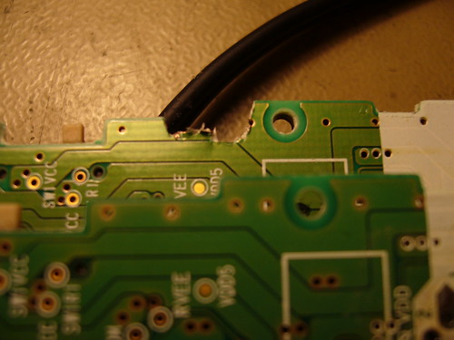
The trick however, to make this mod work, is to cut away a piece of the PCB to make room for the cable. The copper trace that is affected, is relatively wide, so there’s some margin. However, it’s for the power supply, so there’s a small risk that you might need to compensate for the loss in size be adding an extra wire. I haven’t had any problems with this yet, but I guess this would depend on how big a piece of the board you cut away. The only slight problem I had was that the cable just barely fit into the space when reassembling the GBC. But it seems to adjusted itself and it now works beautifully.
Pics:
The wires soldered to the potentiometer. I soldered the wires pre-pot to always get maximum volume and minimum impedance. (I’ll always be connecting it to a mixer anyway.)
The notch in the PCB (Front) - modded vs unmodded board
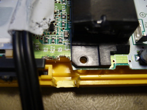
The notch in the PCB (back)
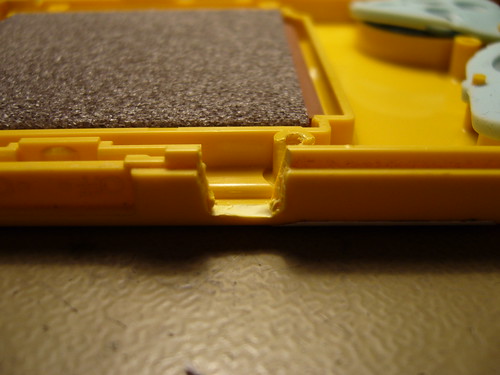
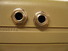
The hole where the cable exits
Zoomed out

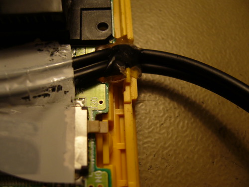
Some hot glue to fix the cable
The final product (Reassembled)
What thinks?
PCB Manufacturing at my university (Pictures)
December 19th, 2008So I etched a PCB at my university today, and i thought I’d share some pictures. Today’s PCB is an XR-2206 Based Voltage Controlled Oscillator, a rad oscillator synth module.
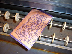
The manufacturing process involves several transfers: Paper -> Photographic film -> Photoresist -> Copper. Let’s begin with a picture of three of the steps, the printed paper, the film and the finished PCB.
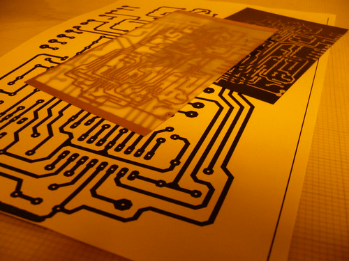
So the first thing I have to do is print the layout on paper. It needs to be printed with high contrast and dense blackness to transfer well to the photographic film. For this PCB I chose to do the transfer double sized to increase the contrast, but you can transfer it with a 1:1 size source printout. (Or anything between)

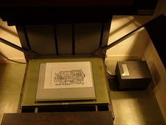
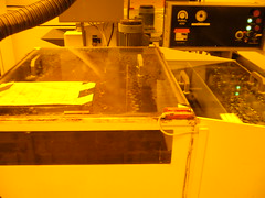
 The next step is to expose the photographic film. This is done with a device consisting of a glass plate under which you put the original, and a lid under which you put the film. Both the glass and the lid have vacuum suction to keep the paper and film in place.
When you press a button, two light sources are turned on to expose the film. The light is reflected against the source material through a lens, and onto the film. The film is, as far as I know standard black and white photographic film. In other words, this device is a giant camera.
The next step is to develop the film. This is done by putting the film first in a “developer” fluid to make the image visible, and then in a “fixer” fluid to protect the film from light. Until the film has been completely developed, the photo room must be lit strictly using a faint red light to avoid exposing the film by accident.

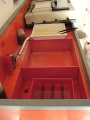
 Next up is transferring the image on the film to the photoresist on the board. Unfortunately I forgot to take a picture of this step, but it’s done by exposing the photoresist to UV light through the film. The photoresist will be weakened in all areas exposed to the UV light. The weakened areas will then be etched away using a CaCO3 (Calcium carbonate) solution in the first etching machine. The result is that the copper is exposed at those parts. (Left picture) And then I put it through the second etching machine, containing iron chloride, which will etch away the exposed copper areas. (Right picture)

Almost done. The last step is to put the board into a stripper fluid (NaOH, Sodium hydroxide) to remove the remaining photoresist.
After drilling the holes the PCB is ready to be equipped with components.
Electronic components (Pictures)
November 2nd, 2008Before my local shop electronic components, Labb Elektronik, (RIP) shut down, they gave away free bags with random stuff. These pictures are the result of sorting the components in these bags. Most of it is pretty useless for what I want to do, apart from building tube circuitry, where the capacitors and high wattage resistors might be useful. But some of the things are pure eye candy!
Each picture has a title attribute - hover an image to see a tooltip, or click it to go to its flickr page.


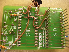
SID2SID with two different SID flavours: Finished
November 22nd, 2007I finally inished my special SID2SID, which has a little hack that allows you to use two different flavours of SID on the same board, at least if used on a 6581 board. The trick is to regulate the 12V used for the 6581 down to 9V, for the 8580. The 8580 should use the same filter caps as 8580 always uses. I don’t remember the value, but the SID2SID manual covers this.
Here’s my test setup:
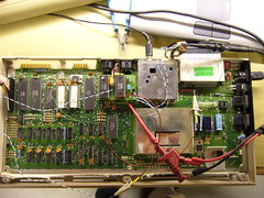
Prophet64 still identifies the main SID, a 6581. On the right, the audio outpus from the SIDs.
And here is a closer look of the little beauty. It’s too much of a snake’s nest, but that was because of a mistake of mine. The left picture is the bottom side of the SID2SID. It’s filled with dirty tricks. The first thing I want to point out is the voltage regulator. It has three wires. For the voltage regulator to have any effect at all, you have to cut the trace to VDD and connect the voltage regulator. (If you don’t know, or can’t find instructions, how to connect a voltage regulator, you probably shouldn’t do this mod, so I won’t tell you the exact wiring.)
I first cut the wrong trace, so there’s one excess wire to fix that.
The regulator should be a 7809, (+9 V regulator) but all I could find was a 7808. (+8 V regulator) That’s 1 V too low, but works, and will hopefully help keep the chip cool. The big cap attached to it was an attempt to keep noise in VDD to a minimum, but didn’t help much. However, it fits perfectly between the IC sockets and keeps the regulator steady in one place.
The resistor on the upper left grounds the SID sound input, which reduces the noise a little. The resistor on the lower left charges DC blocking cap, so that it’s nicely charged when you plug it into something. Hopefully this will help protect the chip, but maybe it will make it burn out faster. Time will tell.
No sounds samples up yet sorry, but it works fine. What doesn’t work fine is joystick port 2, where the fire button seems to be fried from ESD. (I finally realized this) So unless I learn how to use P64 without a mouse, no fun for some time. (But I can still use drummer and bassline of course.)
In the long run, I’d like to implement one or more of AlphA’s C64 mods. I will also try to modify the filter circuit in a strange way, bend if you will. Any news, and you’ll hear it here.
Also, fuckings to ps.
Update: Answer to Joey’s question:
In order to do what you want to you have drop the voltage and replace the caps, yes. The easiest way to replace the caps for SID 1 is to cut the 4 filter legs of the board, and solder 8580 compatible capacitors on the SID2SID board. The SID2SID cover this topic well.
As for regulating the voltage, I advise you to cut off the VDD pin, or possible bend it upwards in some acrobatic manner. That’s where the higher voltage goes onto the SID2SID board, somehow making sure that pin is not directly connect to the 12 V source on the board is crucial if you don’t want to fry two chips in one go. (*Shudders*)
Then you can connect the output of the regulator to that pin you’ve just bent/cut. Ground goes to ground and input goes to input. Crazy as I am, in your situation I would’ve tried to somehow fit the regulator where the VDD pin was. This way you can just put down the chip in the socket and the regulator leg would go in the right place. But that’s overkill, really.
Just make sure the VDD is regulated. And make sure the 12 V you have found is source is actually connected to the power supply. (Put your multimeter in diode mode, and probe the point you’ve found and pin 28 on the SID socket, while the machine is off)
If you need it, here is the SID pinout and the SID2SID manual.
Good luck!
Edit: The lurvtrut was removed in favour for an actual SID pinout.
Three videos (Moshpit 2007, Moxibustor)
September 21st, 2007Please excuse the really crappy quality of these videos, but this all I got at the moment. The first one is a video of me, and the second one is of Boy vs Bacteria. The third video is a video of me playing with The Moxibustor, my glitch oscillator.
Both the videos from Moshpit are shot by Fredrik Stolpe (Cornbeast)
nitro2k01 @ Moshpit Open 2007
Boy vs Bacteria @ Moshpit Open 2007
Me playing with the first prototype of The Moxibustor.
The Moxibustor - A glitchy oscillator
September 15th, 2007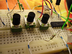
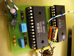
Here we have the second prototype of the Moxibustor glitch oscillator synth. The first prototype had slightly different components, and reminded me of a dub siren in some modes. The second prototype has slightly different components and also a second IC.
What does the Moxibustor do really? It has three knobs and a buttons. Each knob controls the frequency of an astable Schmitt trigger oscillator. The frequency ranges have are different on purpose, so one of the oscillators can go down to down to sub-bass frequencies, and work as an LFO, and one can go up to 1 kHz or so.
The three signals are mixed digitally at the resolution of 1 bit. This clips the three square waves even more, which gives an effect called intermodulation distorsion, which slightly, but not completely, resembles ring modulation. Then there’s also a secondary chip, a decade counter (Just happened to have it lying around :p )
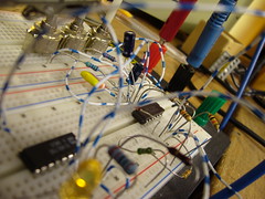
The result is a glitchy thing that offers a variety of glitchy square wave-ish sounds.
But don’t take my word for it, listen for yourself. (Caution: loud)
http://www.gg8.se/music/moxibustor.mp3
If you’re interested in buying a special made piece of this machine, please contact me.