![You suck at protoshop. No, you [i]really[/i] oo.](http://blog.gg8.se/images/you-suck-at-photoshop-you-really-do-your-awful.png)


How to patch your DMG to use a biverted palette
November 23rd, 2009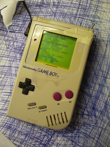
Inverted:
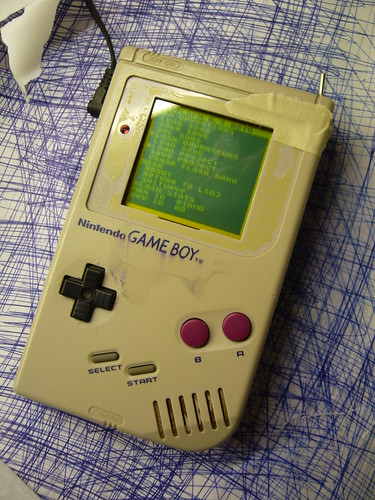
(Please excuse the shabby look, but that is my guinea pig Gameboy that I use for experimentation.)
I’ve already explained how you can invert the monochrome palette in LSDj which is useful if you have a DMG backlight with an inverted polarizer film on your DMG. But what if you want to use a normal palette for other software or games?
Modding the ROM of the game or program you want to invert the palette for is an option, but it may not be practical. Fear not however, the protocol that the DMG is using to transfer data from its all-in-one chip to the LCD is strikingly simple, and can easily be inverted with a 74hc logic circuit of your choice, a so-called biversion.
First let’s have a look at how the protocol works.
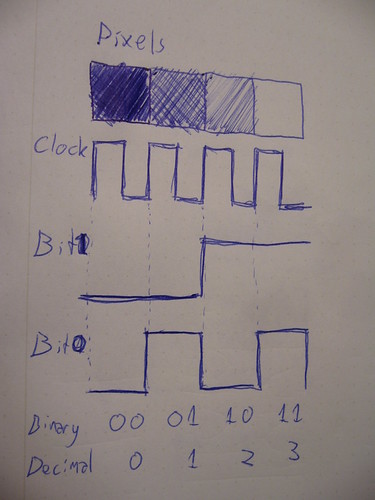
For the sake of this tutorial there are three important pins to keep track of. Data bit 0, data bit 1 and clock. At every rising edge clock edge (when the clock line changes from 0V to +5V) the current state of the data lines is recorded, and the corresponding pixel value is drawn to the currently active pixel on the LCD. This keeps goes until the whole screen is filled with an image. And then again and again. (Ok, there are more aspects to it, like so called “blanking” but that’s not relevant for this discussion)
So what you need to do is change the values of the data lines in such a way that black becomes white, light gray becomes dark gray and so on. The way to do this is by simply inverting the two data bits. There are (at least) two possible ways to do this.
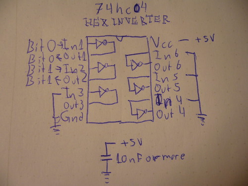
One way is to use a simple inverter like 74hc04, where you connect the data bits to the appropriate input and outputs. Also note two things abut the schematic:
1) I have connected all unused input to ground. (Unused outputs should remain unconnected)
2) I’ve added a bypass capacitor between Gnd and +5V
Neither one of these things are strictly necessary but they are good practice, and may help reduce interference to the signal if that would be a problem.
And obviously you can use any pair of inputs and outputs on the chip.
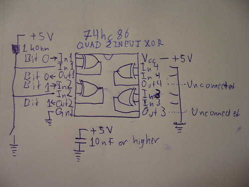
The other way of doing it, which is what I did for my prototype, is to use xor gates. (74hc86) The advantage of that method is that you can switch between the modes easily with a switch. If you xor a bit value with 0, you get back the same bit value. If you instead xor the bit value with 1, you get back the inverted value. So in this configuration, I’ve connected a weak pullup resistor, which sets one of the inputs to 1 by default, meaning the image is inverted by default. However, if those inputs are shorted to ground, the xor operation returns the original data and the picture is again unaffected.
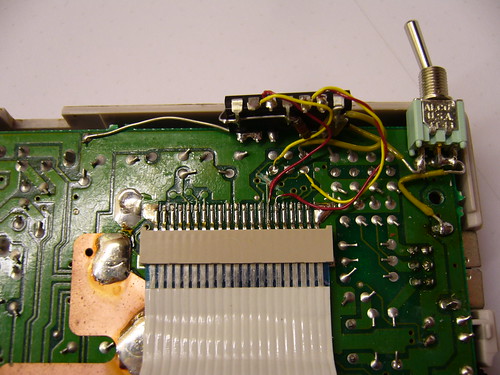
So, how does one actually connect the inverter? You need to cut the copper trace where the data and solder the input and outputs on each side of the cut.
This is what my prototype circuit looks like. I’ve connected the inputs of the inverter to the appropriate holes that are already available in the motherboard, but filled with solder.
A sidenote on these holes: They were most probably placed there to enable connection to the WideBoy unit, which was an official Nintendo development kit that allowed the screen image of a Gameboy to be displayed on a TV with the help of a NES.
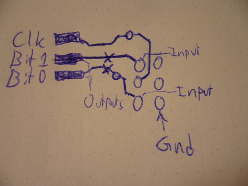
At any rate they come in handy now. The above diagram show you where to tap the input signals, where to cut the traces, and where to solder the output wires. When cutting the traces make sure you cut them properly, or you’ll have a conflict. Do not cut the Clk trace.
All three holes shown to the right in the diagram are connected to Gnd.
Last but not least, a video of the thing in action:
So… Tell me what you think. Is this information useful? Anything unclear? Is my English to quirky and corny? Anyone interested in buying kits for this thing?
The terms “biversion” and “bivert” were later coined for this mod by Bibin.
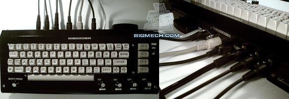
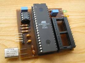
8580 in 6581 Commodore 64?
July 18th, 2007Right now I’m doing a hack to fit a 8580 SID as the second SID in a SID2SID, in a C64 designed for a 6581 SID. The the 6581 uses 12 V power and the 8580 uses 9 V power. So I had to put a regulator to regulate the 12 V down to 9 V. However, I didn’t find a 7809 (9 V linear regulator) so I’m using a 7808 instead. While that won’t fry the chip, the chip may not work because the voltage is too low.
I’ll be back soon to tell you the result. I don’t have a camera, and Veqtor who was too faint at heart (Alternatively just tired) went home. So don’t expect any pictures until at least tomorrow.
That’s all for now. Back in a few minutes.
Update 1: I inserted the SID2SID board into the C64, and turned it on. At first I just got a blank screen but soon realized that I had forgotten to connect the CS wire. After doing that Prophet64 started fine. the 8580 didn’t catch fire, emit smoke or heat abnormally. Test mode reports 6581, which is my main chip, as mentioned. I have yet to check whether it correctly outputs sound. Back with an update soon.
Update 2: I hooked up the sound output of the secondary SID to an oscilloscope, and… Nothing! There was no signal, nothing. I can think of several things that might’ve gone wrong. 8.13 V (That’s what I measured the output from regulator to be) might be too low. I might’ve done something wrong with the VCC connection. (At first I cut the VCC cupper path when I meant to cut the VDD path) I might’ve got the transistor wrong. (I chose another type because I didn’t find any 2n2222) The filter caps are the ones meant for a 6581. (Although that shouldn’t hurt the chip, just offset the filter frequency) Or I might’ve just burned a perfectly good 8580R5.
I will do tests to eliminate these possibilities and report.
Test results:
- The VCC line is ok. (Almost 5 V)
- I put the 8580 back in its home computer, and it’s not fried. When doing so, I measured VDD to 9.25 V.
- I put the 8580 back to the SID2SID, put it back in the 6581 C64, and measured the output from the out pin. The result was a perfectly fine sawtooth waveform, that changed as I changed the test properties. In other words, the mod works, and did so from the start.
- The problem is, in other words somewhere in the post-SID amplification circuit, and in other words, the 8580 works as it’s supposed to.
It generated some heat, but so did the 6581 as well as other IC’s on the mainboard, so I don’t think this a cause for concern. - It seems like my replacement transistor did something wrong. Now I’m out hunting for a real 2n2222
Prophet64 GET
June 11th, 2007I’ve finally decided to make it happen. I have a C64 (Breadbox) that I haven’t been using much, mostly due to the lack of a diskette drive, and in turn software.
I saw this page, featuring a load of tasty mods for the thing. (Mainly audio mods)
Here’s what his C64 looked like when he was done with it:
Doesn’t that just look fabulous? However, myself, I’m planning to paint upper part pink, and the lower, probably black. Ugly you may think, but I think it’ll look… fresh in some way.
I also found this project, SwinSID which is a somewhat compatible SID clone, which I think sounds pretty good. A perfect combination would be to have one SID (To get the raw rough sound) and one SwinSID (To get some smooth wave forms) one a SID2SID. (A little cirucit board that lets you use two SIDs in one C64) I just wonder if SwinSID will work with SID2SID. I have yet to find out!
Anyway, being exposed to both these cool C64 mods within a matter of days, I have finally decided to get Prophet64.
Stay tuned for my report about it later on!
A whole PC in a DMG case
May 10th, 2007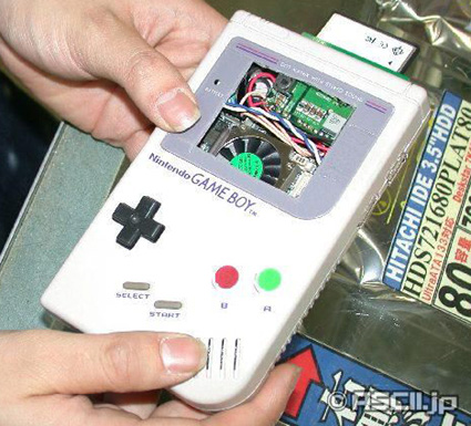
I was hesitating to post about this thing. After all this guy is butching an innocent Gameboy to do this thing. But on the other hand it’s a cool thing, and honestly one that I’d like to own. (Although it’s not as cool as the NES mini, a whole NES, fitted into the size of a NES controller)
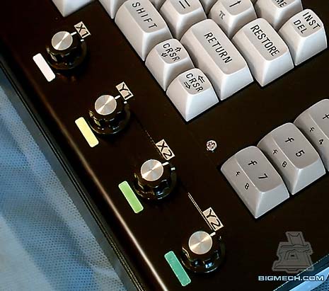
Also the activity LEDs in different colors reminded me of my own yellowboy with one red and on black button.
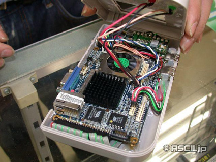
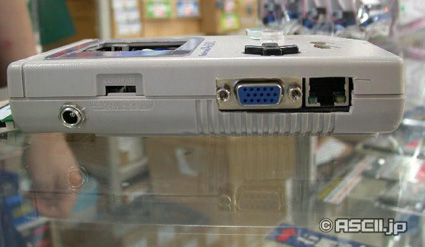
The miniature PC is based on the Via EPIA PX10000G motherboard, a board of the Pico-ITX standard. Even though the small size, it houses connections for VGA, as well as USB and ethernet. One of the USB ports is placed in a very good spot: Where the link port used to be. People often ask me about my classic Gameboys if that port is for firewire (!) They never saw that port on their own GB’s, appearantly because it’s usually covered with a piece of plastic to protect the machine from dust.
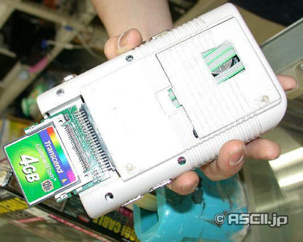
The PC lacks a hard drive, and uses CF cards for storage instead. CF uses the same or almost the same interface as IDE, as far as I know, meaning that you could probably attach IDE drives to it with a little tinkering.
In its current shape, the CF card appearantly stores the OS. The guy is using Windows XP embedded for the purpose, but I’d like to try some flavor of Linux, or possibly Lunix. (No, I’m not serious, I just like to drop that link)
Story chain: Engadget » Plastic Bamboo » Japanese original page
So a little report about the 09 F9 11 02 9D 74 E3 5B D8 41 56 C5 63 56 88 C0 business. At the moment, it’s at 1720000 results, closing in to two millions. Also, digg has decided not moderate articles and comments containing the code. (Which I didn’t discover until today, more than a week too late) And here’s an article about a novel way of expressing the digits, with all the implications involved.
“Takedown This!”
That’s all for today. I’m Joanne and this is Ro… Wait, not really.
Also, 58.70.6.xx-san from Japan (Later using the IP 60.56.165.xx) Please leave a comment! I see that you have reloaded my page a lot or something. I also see that you are an Opera user, just like me. Reveal yourself!