![You suck at protoshop. No, you [i]really[/i] oo.](http://blog.gg8.se/images/you-suck-at-photoshop-you-really-do-your-awful.png)


How to patch your DMG to use a biverted palette
November 23rd, 2009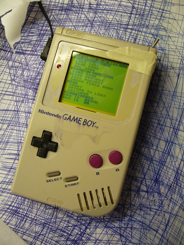
Inverted:
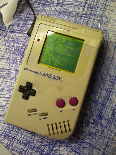
(Please excuse the shabby look, but that is my guinea pig Gameboy that I use for experimentation.)
I’ve already explained how you can invert the monochrome palette in LSDj which is useful if you have a DMG backlight with an inverted polarizer film on your DMG. But what if you want to use a normal palette for other software or games?
Modding the ROM of the game or program you want to invert the palette for is an option, but it may not be practical. Fear not however, the protocol that the DMG is using to transfer data from its all-in-one chip to the LCD is strikingly simple, and can easily be inverted with a 74hc logic circuit of your choice, a so-called biversion.
First let’s have a look at how the protocol works.
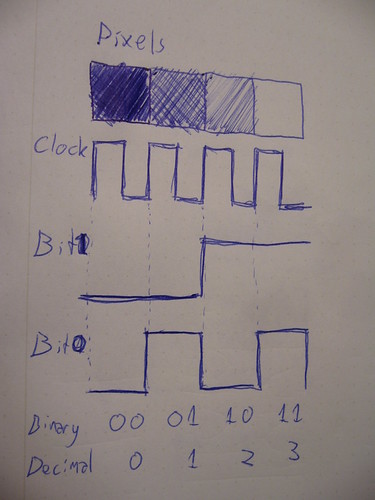
For the sake of this tutorial there are three important pins to keep track of. Data bit 0, data bit 1 and clock. At every rising edge clock edge (when the clock line changes from 0V to +5V) the current state of the data lines is recorded, and the corresponding pixel value is drawn to the currently active pixel on the LCD. This keeps goes until the whole screen is filled with an image. And then again and again. (Ok, there are more aspects to it, like so called “blanking” but that’s not relevant for this discussion)
So what you need to do is change the values of the data lines in such a way that black becomes white, light gray becomes dark gray and so on. The way to do this is by simply inverting the two data bits. There are (at least) two possible ways to do this.
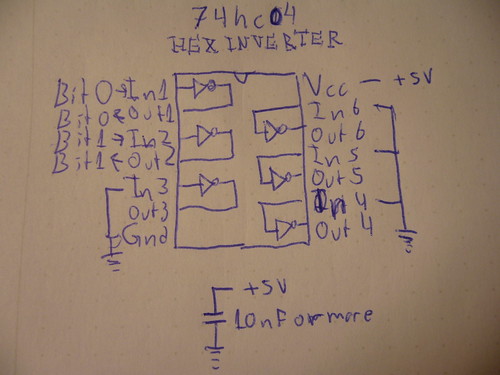
One way is to use a simple inverter like 74hc04, where you connect the data bits to the appropriate input and outputs. Also note two things abut the schematic:
1) I have connected all unused input to ground. (Unused outputs should remain unconnected)
2) I’ve added a bypass capacitor between Gnd and +5V
Neither one of these things are strictly necessary but they are good practice, and may help reduce interference to the signal if that would be a problem.
And obviously you can use any pair of inputs and outputs on the chip.
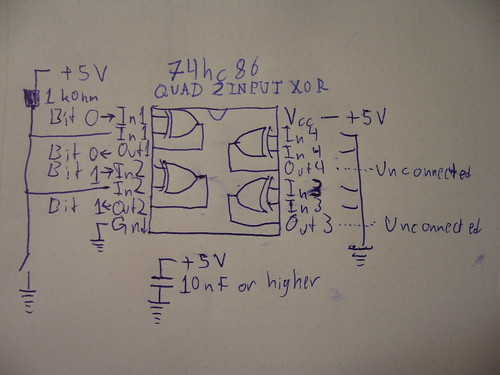
The other way of doing it, which is what I did for my prototype, is to use xor gates. (74hc86) The advantage of that method is that you can switch between the modes easily with a switch. If you xor a bit value with 0, you get back the same bit value. If you instead xor the bit value with 1, you get back the inverted value. So in this configuration, I’ve connected a weak pullup resistor, which sets one of the inputs to 1 by default, meaning the image is inverted by default. However, if those inputs are shorted to ground, the xor operation returns the original data and the picture is again unaffected.
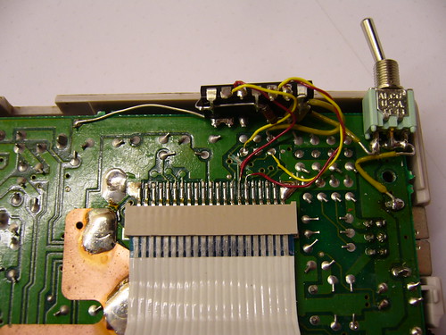
So, how does one actually connect the inverter? You need to cut the copper trace where the data and solder the input and outputs on each side of the cut.
This is what my prototype circuit looks like. I’ve connected the inputs of the inverter to the appropriate holes that are already available in the motherboard, but filled with solder.
A sidenote on these holes: They were most probably placed there to enable connection to the WideBoy unit, which was an official Nintendo development kit that allowed the screen image of a Gameboy to be displayed on a TV with the help of a NES.
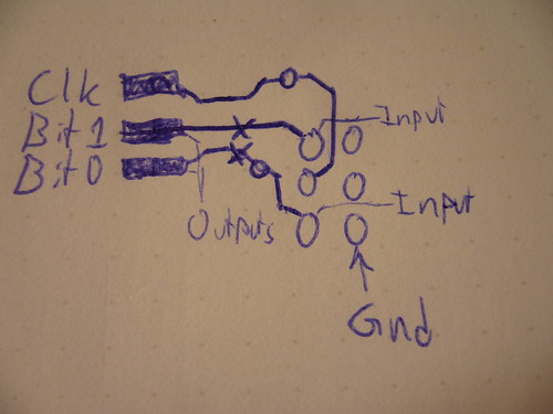
At any rate they come in handy now. The above diagram show you where to tap the input signals, where to cut the traces, and where to solder the output wires. When cutting the traces make sure you cut them properly, or you’ll have a conflict. Do not cut the Clk trace.
All three holes shown to the right in the diagram are connected to Gnd.
Last but not least, a video of the thing in action:
So… Tell me what you think. Is this information useful? Anything unclear? Is my English to quirky and corny? Anyone interested in buying kits for this thing?
The terms “biversion” and “bivert” were later coined for this mod by Bibin.
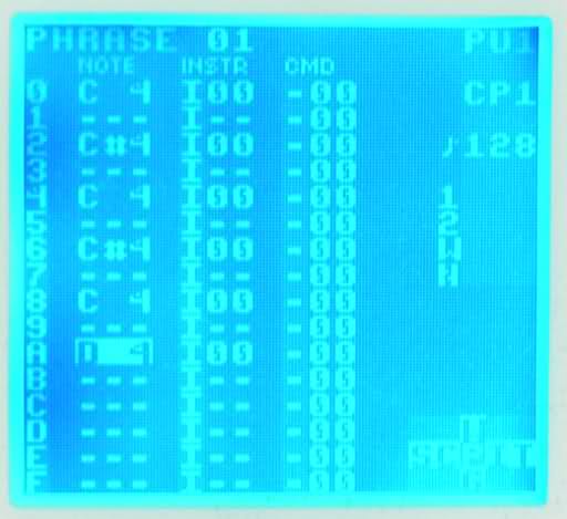
Pictures of inverted palette LSDj running on an inverted DMG screen
November 2nd, 2009Blue standard polarity (?) DMG screen running LSDj with an inverted palette
Red inverse polarity DMG screen running LSDj with an inverted palette
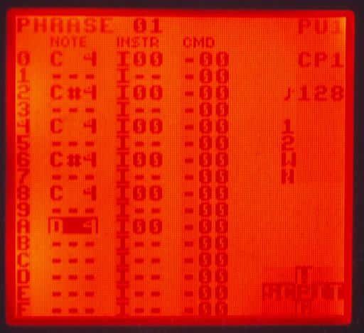
Thanks 30003019 for the pictures. He comments “anyway, it makes the inverted red backlight a lot less painful to the eyes”.