![You suck at protoshop. No, you [i]really[/i] oo.](http://blog.gg8.se/images/you-suck-at-photoshop-you-really-do-your-awful.png)


Fixing Gameboy-powered Arduinoboy MIDI glitches
July 26th, 2009I recently had a little problem when building my Arduinoboy. The Arduinoboy did appear to work, but it was glitchy. Some MIDI notes were ignored or gave strange results, and sync didn’t appear to work at all. I sat down and compared trash80’s schematic to other MIDI 6n138 schematics and I noticed something: There was not resistor between pin 7 and ground in trash80’s schematic, which is is otherwise common in MIDI optocoupler circuits.
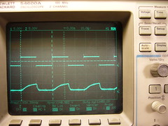
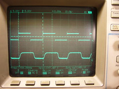
Left: Before, Right: After. Upper waveform: Test signal source, Lower waveform: Opto-coupler output. Both powered by the Gameboy.
So I set up a prototype circuit with a test signal of 32 kHz to see if I could trace the problem. It turned out that the problem only happens when you power the Arduinoboy from the Gameboy. When powering it with +5V it worked alright and the oscilloscope output looked ok. However when powering it from the Gameboy, the combined losses from the lower output voltage from the Gameboy (The DC/DC only outputs 4.8 V as shown in the previous post) the protection diode at the Gameboy’s link port and trash80’s way of driving the 6n138 resulted in a source voltage of 4V for the 6n138 which made the rise time way to high, as you can see in the left picture.
Adding a 4.7k resistor between pin 7 of the 6n138 and ground decreased the rise time enough to make the circuit work flawlessly. So if you’re having problems with a Gameboy-powered Arduinoboy, try this. Fixed version of trash80’s schematic provided below.
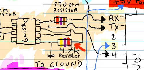
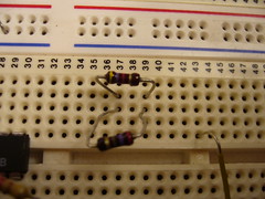
And finally a word of caution. Don’t confuse the 4.7k resistor with the 270 Ohm resistor. A 270 Ohm resistor with a 5% mark (gold strip) can look confusingly similar to a 4.7k resistor. Can you tell the difference below?
July 26th, 2009 at 5:27 am
plan to build an arduinoboy within the year if not the first half of next year provided I have the funds and the time. I dont understand much of what has been said here but it sounds like you solved a power issue. so thank you. Ill bookmark this for future reference. you’re the best nitro. =)
July 27th, 2009 at 6:27 am
Sweet. and whoops. I only had problems when the battery life was low. will add this in and update the site as soon as i’m home. Bad ass work as usual nitro2k01!
July 27th, 2009 at 2:47 pm
Fantastic work, nitro2k01.
August 10th, 2009 at 9:25 pm
I tried this with a an ac adapter powered dmg-01 powering the arduino and anytime a midi message was sent to mgb the gb screen faded and came back after said midi event. No sound would output from the gb either. removed resistor and it was fine (with original glitches and missed midi events back). I’ll try a diff’t gb, alternate adapter (non Nintendo), and batteries. I will also try powering the arduino independently.
August 10th, 2009 at 9:39 pm
Are you sure you used the right resistor value, and connected everything correctly?
My qualified guess is that you either used a much too small value for the fixing resistor I suggested or that you (previously) connected pin 6 of the opto-coupler. (2nd from the bottom on the right side) to V+. Is either of that true?
June 23rd, 2014 at 6:21 am
[...] – finally managed to make one. Used the original schematic of course with nitro20k1′s fix. The circuit requires 6N138 optocoupler and I purchased some off ebay a while go. Now I discovered [...]
May 16th, 2019 at 1:13 pm
[...] saw this link: Fixing Gameboy-powered Arduinoboy MIDI glitches and tried a 4.7K from VB (pin 7) to ground and it looks so much better (bottom [...]