![You suck at protoshop. No, you [i]really[/i] oo.](http://blog.gg8.se/images/you-suck-at-photoshop-you-really-do-your-awful.png)


Dell PSU third pin fix
April 25th, 2014A few years ago, I bought a PSU for my Dell D600 on eBay which turned out to be a really crappy Chinese pirate PSU which suffered badly from interference. When I wanted to fix the interference by connecting the plug to a different, and genuine Dell PSU, I stumbled upon a problem. All modern Dell PSU’s have a ID feature to confirm that the PSU is genuine, using a 3rd pin center pin connected to an EEPROM. If this chip does not match, the laptop won’t allow the battery to be charged. While a less scrupulous 3rd party manufacturer can nag one of those ID chips from a broken genuine Dell PSU and pass the test with a any poor quality PSU, I had to transplant this ID chip somehow, to make the PSU work.


I recently got another Dell laptop with a broken PSU, which I could have if I could fix the PSU. Like last time, I decided to splice the cable with a board containing the chip.

This board was made from veroboard, and ws a bit bulky, so I decided to design and order a new one. This posted is an illustrated guide to how this board is used.

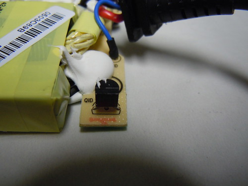
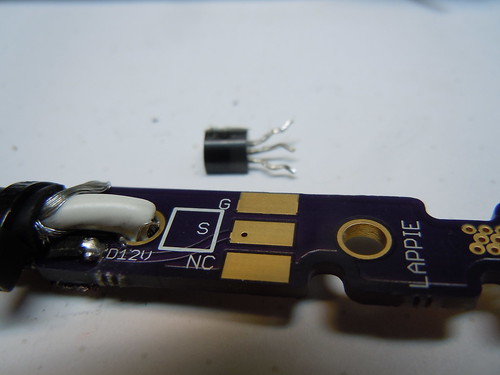
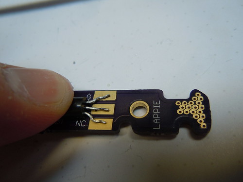
To use this board, it is assumed you already have a working ID chip, a three pin Dell plug, and a working PSU that can deliver 19-20 V at the required wattage. The ID chip could come form either a broken Dell charger, or a pirate PSU (which in turn probably got its chip from a broken PSU.) Here’s our victim, the TO92 package chip marked QID. Desolder this chip. Optionally snag the zener diode (the small black component) and the 130 ohm resistor (marked 1300).
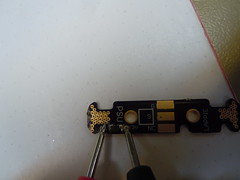
First, file down the board edge around the snap-off points to prevent sharp edges that may puncture the heatshrink tubing that will be used lately. I also rounded the edges, as I neglected to round them when designing the board.
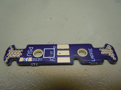
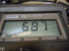
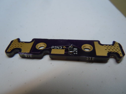
Attach the zener diode to the footprint D12V. This component is polarized, meaning that the orientation of it matters. When oriented correctly, it should show diode voltage drop of around 0.7 V, when probed in your multimeter’s diode mode as indicated in the images below. (Note that the right multimeter probe is black, ground and left probe is the test probe, red.) This component may be omitted, which would offer less protection in case of a short circuit between the positive power conductor and the center ID wire.
Attach the 130 ohm resistor. In case you don’t have a 130 ohm resistor, the E12 standard values 120 ohm or 150 ohm will work as well. As you might be able to notice, the footprint is slightly too small for the footprint I had designed for, but it turned out ok anyway.
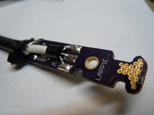
Take your working PSU and cut the cable and peel it. Peel the inner conductor (positive voltage) and leave a suitable length of isolation to be able to feed it through the hole. Make sure you don’t nick the isolation of the inner conductor, risking a short-circuit between the two. If your cable is different, ensure that you are aware which conductor is the negative and positive voltage.
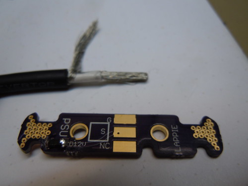
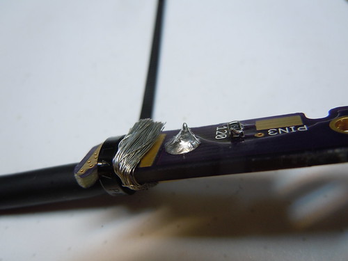
When you are confident that the peeling is done correctly, attach the cable firmly using a cable tie which attaches to the cut-outs in the board. You will also be routing the negative voltage wire (in this case the shield of this coaxial cable) through to the bottom side, through the one cut-out that is bigger than the other. If your cable is different, again ensure that you know which wire is which.
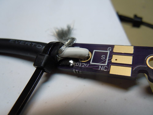
Trim the positive conductor so that it’s almost flat to the board surface.
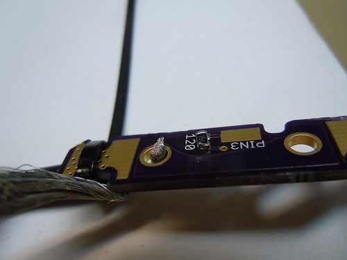
Apply solder. Trim the negative conductor such that it reaches across the big pad.
Apply solder. Ensure proper wetting of the solder joint. Feel free to trim any strands that didn’t stick, to avoid that they deform and create shorts.
At this point, ensure that the positive conductor, going through the hole, doesn’t short anything else, including the right terminal of the zener diode. (The other terminal may however short to ground as shown here, as it is already soldered to ground.)
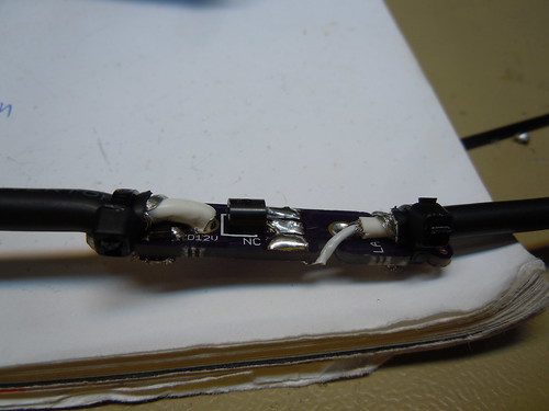
The ID chip should now be placed on the board, with the flat side facing down and each leg connecting to one of the pads. Start forming the legs. When soldering the components into place, you may want to start with the NC (not connected) pin as it is not connected anywhere and has the least thermal and is the easiest to solder. End with the G (ground) pin as it has the largest thermal mass.
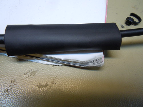
Now it is time to prepare a suitable piece of heatshrink tubing, as it may be impossible to get piece over the plug if you try to do this step after attaching the plug end. Find a diameter of tube that fits snugly over the PCB. Cut a length that is slightly longer than the PCB. Move the tubing over to the wire for later use. I’m using two layers of tubing for redundancy.
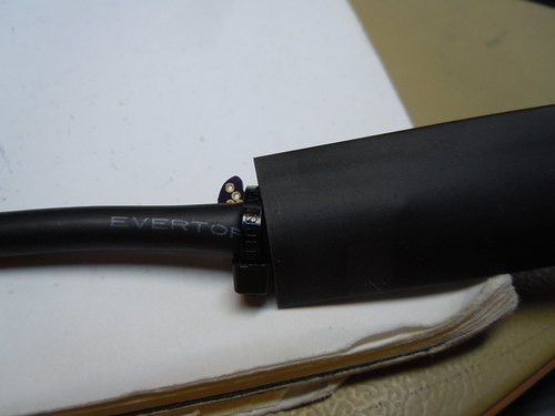

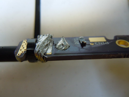
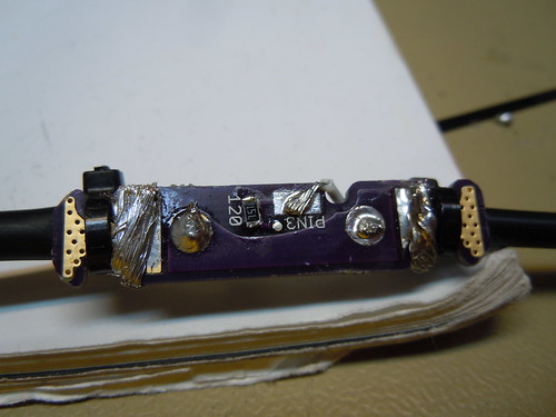
Get the cable end with the plug. Similar to before, prepare the cable by peeling it and leaving appropriate amounts of isolation. Attach the cable using a cable tie. Wrap the outer (negative/ground) connector around the bigger cut-out, to the bottom side and solder it to the big pad. Route the middle connector (positive voltage) through the hole, trim its length and solder it in place. Route the innermost connector, the ID wire, through the extra cut-out and solder it to the PIN3 pad.
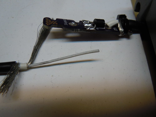
Now, make sure there are no shorts circuits where you don’t want them. If you dare, power up the PSU without plugging it in to the laptop. Measure the voltage between the ground/negative pin and the positive voltage pin. It should show around 19-20V. If it shows lower than what is specified for the PSU, you may have a short circuit.
Ensure that the voltage between ground/negative, and any point connected to the ID chip reads 0V. If any point reads a higher voltage while not plugged in to the computer, you have a short between the ID wire and the positive voltage wire, which may be fatal for the computer when plugged in.
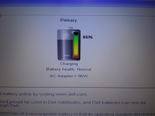
If everything seems ok, try plugging it in. The BIOS should indicate which type of PSU it thinks is connected.
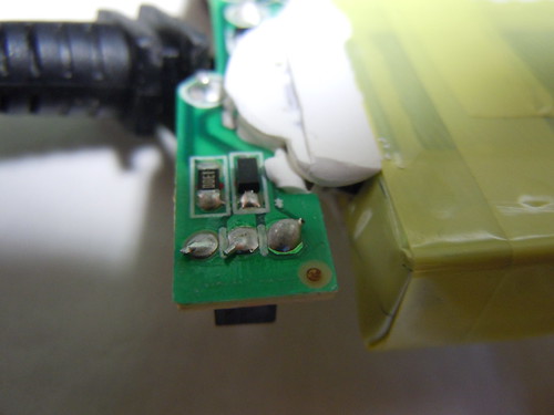
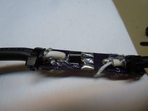
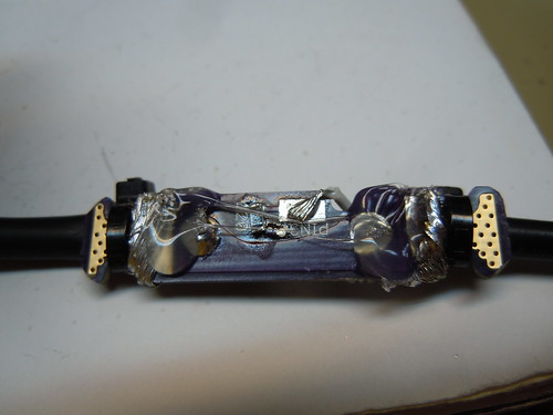
Lastly, I added a bit of hot snot to some strategic locations to prevent short circuits by, say, having a strand of a cable coming lose.
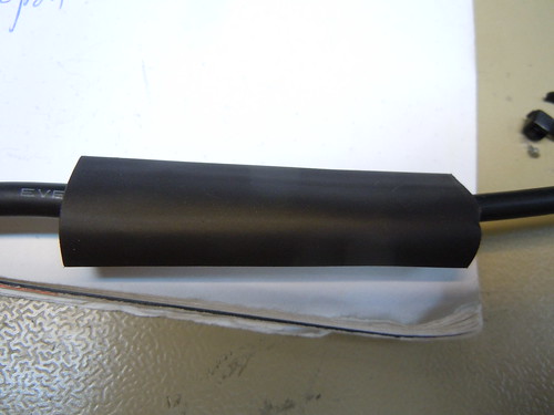
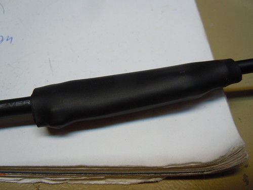
Double check that the BIOS identifies the PSU correctly. Then apply the heatshrink tubing. First one layer…
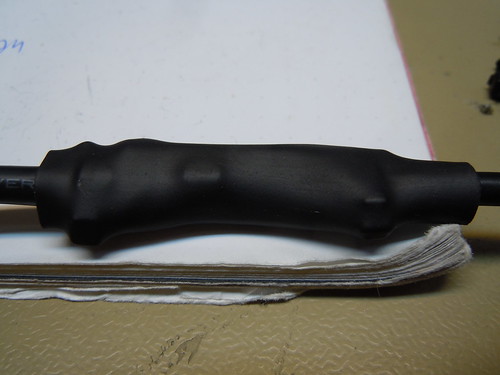
Then a second layer.
That’s all. You now have (assuming you used a good PSU and followed the instructions) a PSU that works with Dell laptops. If there is a demand, I might share the board files and/or make the board available for sale as a shared project on OSHPark.
May 16th, 2014 at 12:31 pm
Hi !
i’m wery happy to read your article. If you would have some of the pcb i would buy some from you… I have a dell laptop and i need it for the car charger from HP and for my home charger too…
Thanks:
fri
November 5th, 2014 at 12:27 am
hi, can you tell me what transistor you used or make a picture close to transistor thanks
March 1st, 2015 at 1:22 pm
As you see…. it is not transistor…. it is ID chip… idiot
April 29th, 2017 at 6:16 pm
no trasistor friend that is ic chips DS2501 please check datasheet
June 7th, 2017 at 9:48 am
Hi can you please upload the PCB files to OSHPark?
Thanks