![You suck at protoshop. No, you [i]really[/i] oo.](http://blog.gg8.se/images/you-suck-at-photoshop-you-really-do-your-awful.png)


Korg monotribe Firmware 2.0 analysis
December 4th, 2011As has already been established, Korg monotribe is MIDI capable. Howver, it is still limited with regard to certain things, such as being able to use more than 8 seqeuncer steps for the synth part or using a filter envelope separately from and LFO. All things that should be very much technically possible on the microcontroller device in the unit. One thing I’ve considered is to modify or even rewrite the firmware of the ‘tribe. Apart from the obvious work of actually rewriting the firmware, you need a way of flashing it onto the device. And preferably a copy of the original firmware, so the ‘tribe won’t be a useless brick until development is done. The microcontroller in the monotribe does support JTAG, a protocol for reading and writing firmware data, among other things, but this function may be locked down for security reasons.
Korg recently announced the 2.0 firmware for the monotribe, which actually gives you 16 step, velocity control and a few other new features. More full information and download available on Korg’s homepage.
But what’s interesting about this upgrade is how you install it. You hold a secret key combo of three buttons on startup to go into upgrade mode, and then play a special audio file into the sync jack to perform the actual upgrade. This is potentially an easy way to hack the firmware of the monotribe (although with the same risk of bricking.)
Below, I’m posting the first step towards that goal, to extract the firmware image from the audio file. First, a big thanks to Th0mas for doing the initial groundwork of figuring out how the data is encoded. In fact, my code below below relies on having a transformed and cleaned up version of the audio data.
How is this data composed? The audio file encodes individual bits as little square wave pieces that are longer or shorter depending on whether a bit is low or high. The problem then becomes to figure out what is high and what is low, and how individual bytes are arranged. Th0mas quickly found out that short pulses mean a logical 1 and that bytes are transmitted with least significant digit first.
The problem, then, was to align the different data packets in the file, which both me and Th0mas spent some time trying to bruteforce by inserting bits at variious places to make the bytes appear correctly. To your you have two plaintext text strings saying KORG, and also a few other patterns. You feel like you’re trying to solve the GCHQ challenge. Eventually I gave a up bruteforcing and made an assumption about the encoding that turned out to be correct.
My starting point was a file with a list of individual bits. The data is transferred in packets with a 256 byte payload each. Normally, a number of 1 bits a retransmitter. To initiate communication, one 0 bit is transmitted, followed by starting signature of 0xA9, then 256 bytes of data are transferred. Then, 3 byte signature, 0×55, 0×55, 0×55 is transmitted (a “checkerboard” pattern, or alternating 0s and 1s.) Lastly, there’s a byte that I’m not sure what it’s for. It’s probably some form of checksum, but I can’t figure out what it is. (I’ve tried a number of xor combinations to see if I could figure it out, but no luck so far. Suggestions are welcome.)
Between every packet, there’s a number of bits skipped, or transmitted as simply 1. 344 to be precise, or 43 bytes. This was probably chosen to get a nice-looking number of cycles for (256+43=99) However, I would still assume that the ‘tribe is triggered by the start bits coming after a pause, rather than counting cycles.
Two packets are different, however, the first and the last. Both have the 0xA9 pre-data signature, and both lack the 0×55 post-data signature. The first, “greeting” package is much shorter than 256 bytes, and the rest is filled with 0xff. It looks like this:
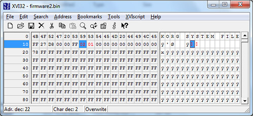
I have not figured out what the 27 D8 value is. I couldn’t find any way of making it match the size of the rest of the dat. The 02 and 01 probably denote that this is version 2.0, first revision.
The last packet is also missing post-data signature. All the regular data adds up to a total of exactly 32768 nytes, or 32 kB.
Below is my version of the decoder program, which takes a “bits” file generated by Th0mas’ scripts, see the link above. It doesn not save the additional data, only the 256 byte payload of each packet.
Code, written in Python: (Or as a pastebin.)
from struct import pack

class TribeDecodeError(Exception):
    def __init__(self, value):
        self.value = value
    def __str__(self):
        return repr(self.value)

# Seeks a 'tribe fw bit array for the next packet start.
# Takes an iterator
def packetseek(it):
    numbits = 0;
    while(it.next()):
        numbits += 1;         # Loop through all the junk bits

    # print "%d bits skipped." % (numbits)

# Fetch next byte from bitarray.
# Returns an int.
def fetchbyte(it):
    tempstr="";
    for x in range(0,8):
        #print it.next()
        tempstr = str(it.next())+tempstr;

    return int(tempstr, 2)

# fetch a number of bytes to extract a full packet
# The second optional argument is to ignore the post-signature check, needed for the initial greeting packet
def fetchpacket(it, ignorepostsig=False, packetindex=0):
    tempbyte=0;tempstr = "";temparray=[];

    tempbyte=fetchbyte(it);

    # Confirm pre-signature
    if(tempbyte != 0xA9):
        raise TribeDecodeError(”Invalid packet pre-signature! Should be 0xA9. Found: ” + hex(tempbyte));

    # Confirm post-signature
    for x in range(0,256):
        tempbyte = fetchbyte(it);
        tempstr+=pack(”B”, tempbyte);
        temparray.append(tempbyte);

    if not ignorepostsig:
        # Confirm post-signature
        for x in range(0,3):
            tempbyte = fetchbyte(it);
            if(tempbyte != 0×55 and packetindex != 0×80):
                raise TribeDecodeError(”Invalid packet post-signature! Should be 3*0×55. Found: ” + hex(tempbyte));

        # Print the mysterious checksum byte
        tempbyte = fetchbyte(it);
        print “Packet %s has checksum (?) %s” % (hex(packetindex), hex(tempbyte));

        # Sanity check
        tempbyte = fetchbyte(it);
        if(tempbyte != 0xff):
            raise TribeDecodeError(”Sanity check. Packet should be followed by 0xff but isn’t. Found: ” + hex(tempbyte));

    return tempstr;

# main function
def tribefwdecode(infile, outfile, invert):
    f = open(infile, “r”);

    bitarray = f.readlines();  # Fetch the array of bits

    # Validate the bit array and convert it to bool
    for i,b in enumerate(bitarray):
        b = b.strip();
        if (b != “0″ and b != “1″):
            raise TribeDecodeError(”Only 0 and 1 in the bit file, please! Found: ” + b);
        else:
            if invert:
                bitarray[i] = 1-int(b);
            else:
                bitarray[i] = int(b);

    bititer = iter(bitarray);

    # Seek for the greeting packet.
    packetseek(bititer);
    fetchpacket(bititer, True)

    f = open(outfile, “w”)

    packetidx = 0;

    while True:
        try:
            packetseek(bititer);        # Try to get a packet
        except StopIteration:
            break;                      # Detect end of file.

        # Parse packet and write it fo the file.
        packet = fetchpacket(bititer,False,packetidx)
        f.write(packet)

        packetidx += 1;

    # If we’re done, close the file.
    f.close();
    print “File %s successfully parsed and written to %s” % (infile, outfile)

tribefwdecode(”bits”, “firmware2.bin”, True)
If you have questions or suggestions what the unknown values might be (27 F8 and checksum) please leave a comment below.
December 4th, 2011 at 1:32 pm
My best guess is that 27D8 is just a magic
(in the firmware data, you can find the entire “KORG FILE SYSTEM” header string wih the trailing “FF 27 D8 00″, must be used to check if a new update has the valid format)
December 4th, 2011 at 5:01 pm
Ludo, it seems like you’re right. There’s another occurrence of KORG SYSTEM FILE in the file, and it’s directly followed by FF 27 D8. So that’s probably it.
December 5th, 2011 at 12:04 am
And the checksum is just the sum modulo 256 of the bytes of the paquet data (without the 0×55).
December 5th, 2011 at 12:29 am
*(without the 0xA9 and the three 0×55)
my decoder: https://gist.github.com/1431500
December 14th, 2011 at 7:35 pm
So has anyone tried analysing the firmware binary yet? Is the processor architecture known?
December 29th, 2011 at 5:31 am
I’m pretty sure the 43 bytes are to give the hardware time to consume the 256-byte buffer, e.g., to write it to flash. I wrote a real-time Arduino decoder (https://github.com/sowbug/TribeDuino). Given the memory and time constraints, I couldn’t imagine doing anything useful with the packet data without the 75-millisecond delay provided by these sync bytes.