![You suck at protoshop. No, you [i]really[/i] oo.](http://blog.gg8.se/images/you-suck-at-photoshop-you-really-do-your-awful.png)


Pushpin Gameboy MIDI cable build report (Failed)
November 29th, 2007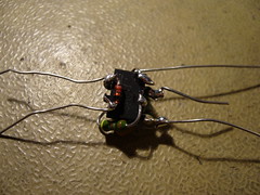
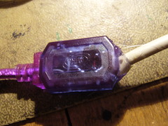
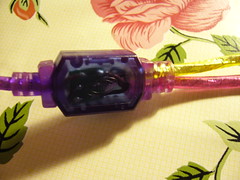
Lower right picture: Original junction box.
Summary: If you bought the components listed on my instruction page, you may want to wait a little for further instructions before you put it together. Some things may be wrong in that schemativ (Most probably resistor values.)
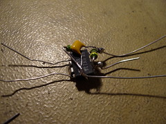
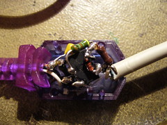
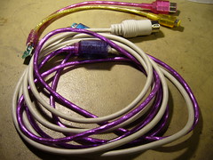
Time for a build report of my brand new Pushpin MIDI cable. First the positive things: I managed to build it as planned, and fit it into smoothly into the little plastic junctions box. The reason I did it this was because I was inspired by AlphA’s ninja style soldering.
It even went so smooth, and looked so nice that I was convinced that it would work right away. Unfortunately, no even close to the truth!
Pushpin didn’t react at all. After testing a lot of different things, I finally ripped the box open again. I had connected the MIDI cable the wrong way around. Damn. And the circuit, as you can see, is very compact, and was also glued to the box to keep it stable. I was forced to clean off the pins and connect the MIDI to the opto-coupler LED withut any additional components. Still didn’t work.
It was about at that time I started to work on a simple test program to indicate whether there is any traffic on the so called SD pin on the link port, which is what Pushpin is using to read MIDI data. The program can be downloaded here: SD Pin Monitor. However, when trying it out, my sound card suddenly stopped working. No$gmb froze when using sound, and most other programs returned an error. I have no clue why. A reboot helped, but it still delayed me a bit.
Still didn’t work. It was not until I connected the MIDI straight to link port that things started giving a hint of working. (MIDI Gnd <-> GB Gnd and MIDI signal <-> GB SD pin) Doing it that way, the test program started responding. Even Pushpin started playing a couple of random notes, although it was nothing of what I actually played, and it was a bit random, not every note returned a sound from PP.
So, here I am, with my cable interface destroyed, not knowing what the problem was. It’s annoying because there are several possible error sources, like:
- Badly timed output from my keyboard (A Radium49)
- Construction error in the adapter I built. (Short circuit or lose contacts)
- Wrong resistor values in my schematic may have blocked the signal somewhere across the way.
I will try to do a more scientific troubleshooting on my school’s lab, where I have access to oscilloscopes and prototype boards, to see if I can trace down the problem. So for now, if you’ve bought the components for the schematic I described before, you may want to wait a while for my results.
On the other hand, it would be cool if one or three people could build my circuit to see if it was just something I did wrong when I built mine. I don’t know. In not too long, we’ll know.
December 1st, 2007 at 5:45 pm
The ninja style soldering is so awesome. Too bad it didn’t work. I think the best plan of action would be to use a breadboard to figure out the resistor values, then make a proto board.
Good luck!
February 22nd, 2008 at 8:13 am
I think the chip in your picture reads 6n136 while bills is a 6n138. I dont know if these 2 chips function th same or even have the same pinouts.
Might be worth looking at.
Good Luck,
Jesse
Jesse’s last blog post..Trippin Static