![You suck at protoshop. No, you [i]really[/i] oo.](http://blog.gg8.se/images/you-suck-at-photoshop-you-really-do-your-awful.png)


GBC Prosound idea
September 13th, 2009Sorry for the blog hiatus during and after my vacation. Before the vacation I came up with a new way of routing the audio cable that I don’t think I’ve seen before. (Feel free to correct me.) Most GBC prosound mods I’ve seen are based in the idea of routing the cable downwards to the bottom of the board.
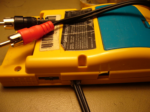
My idea on the other hand is based on connecting the audio wires to the potentiometer as usual, then routing the cable over the PCB, so that it sits below the cartridge when the GBC is reassembled. The cable would then exit through a hole on the right side of the of unit.
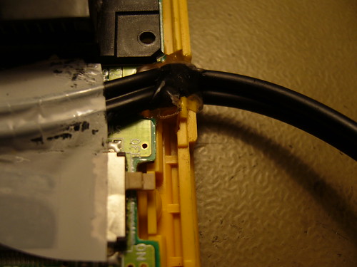
The trick however, to make this mod work, is to cut away a piece of the PCB to make room for the cable. The copper trace that is affected, is relatively wide, so there’s some margin. However, it’s for the power supply, so there’s a small risk that you might need to compensate for the loss in size be adding an extra wire. I haven’t had any problems with this yet, but I guess this would depend on how big a piece of the board you cut away. The only slight problem I had was that the cable just barely fit into the space when reassembling the GBC. But it seems to adjusted itself and it now works beautifully.
Pics:
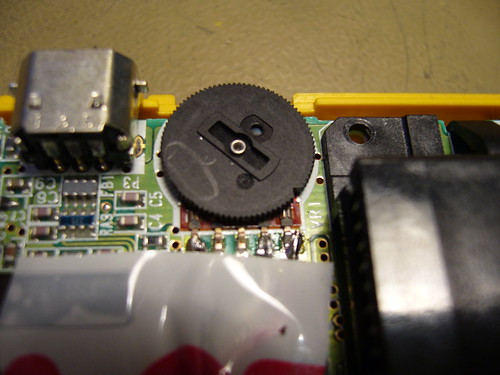
The wires soldered to the potentiometer. I soldered the wires pre-pot to always get maximum volume and minimum impedance. (I’ll always be connecting it to a mixer anyway.)
The notch in the PCB (Front) - modded vs unmodded board
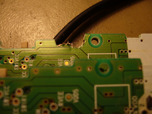
The notch in the PCB (back)
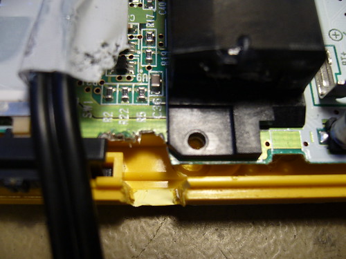
The hole where the cable exits
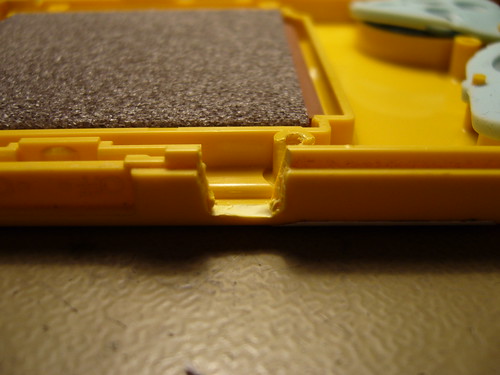
Zoomed out

Some hot glue to fix the cable
The final product (Reassembled)
What thinks?
September 13th, 2009 at 6:36 pm
can i possibly see a better picture of the leads soldered to the pot? i’ve never seen them in those spots and i kind of wanna try this out with some RCA cables and GBCs i have lying around.
September 13th, 2009 at 7:07 pm
Here’s a closeup
I put some shrinkwrap around the ground/isolation so they couldn’t short anything. (Poor man’s solution, put a layer of plastic adhesive tape under the cable when you’re done soldering) Be careful at the splice point that the ground wires is facing up, for the same reason.
Don’t peel the wires more than needed. Presolder the wires and the potentiometer pins. (Heat them up and melt some solder into them, but just for the solder to melt) This makes it easier to attach the wires.
Tape the cable to the motherboard, at exactly the right distance from the pot. With a steady hand and a pair of tweezers, bring the one wire to the correct potentiometer pin and give it a go with the soldering iron. Keep the wire completely still until the solder has become solid. Repeat for each wire.
Hope that helped.
September 13th, 2009 at 7:52 pm
thanks im gonna do this right now! that picture is beyond perfect.
September 16th, 2009 at 6:27 am
wow!!
hahaha!!
so simple and easy idea!!
I love it.