![You suck at protoshop. No, you [i]really[/i] oo.](http://blog.gg8.se/images/you-suck-at-photoshop-you-really-do-your-awful.png)


How to build a MIDI interface for Pushpin
November 28th, 2007This is a guide inspired by and loosely based on this Pushpin guide. However, there are a couple of things that I’d like to remark on, and one thing that is actually plain wrong.
Update: I built and tested my interface, and it didn’t work out as I wanted it to. I will do more thorough troubleshooting in a few days. You can read the full build report here.
If you bought the components listed below, you may want to wait a little for further instructions before you build it. Some things may be wrong in that schematic (Most probably resistor values.)
Update 2: I’ve made a new schematic based on a working device built by Bill Byrne/PLI. You can see how it looks here: http://www.billbyrne.net/pushpinworks.jpg
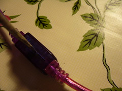
Finding the right link cable
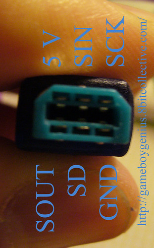
First you need a link cable to use for the interface. There are special requirements for the cable. It has to have cables for all six of the pins, and it has to fit the Gameboy Color link socket. This means that neither a big plug, as used for DMG’s (Grey Gameboys) or a GBA only plug with an extra piece of plastic, can be used.
What this means in terms of finding the right cable, is that it’s a bit of a gamble to find the right one. One thing is for sure though: Stay away from Nintendo’s official Gamelink cables. They’re guaranteed not to have wires to all 6 pins. Look for a 3rd party cable instead. Some cables are sold as GBA cables but can in fact in fact be plugged into a GBC socket.
The picture farther down shows a working cable with pinouts. Ans easy way to tell that a cable is not working, is if there’s no connector for the 5 V and SD pins.
If you find a source for working cables, please leave a comment!
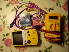
Getting access to the wires in the cable
You can just cut the cable in the middle if you want to, but my cable also has a little plastic box where the cable is split three ways, two GBC plugs, and one DMG plug. I will try to re-use for the circuit, if I can get it small enogh to fit into it.
The best way to open a little box like this one is to force something sharp, like scalpel between the two pieces and force them apart. I don’t have scalpel, so the next to best option for me use a screwdriver. I couldn’t fit it in the gap, so instead I applied quite large amount of pressure in the center of it, which made the pieces come apart, at the expense of a small piece of plastic. However, this piece wasn’t critical and I can still put the pieces together.
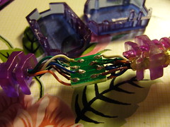
Tracing the wires in the cable
The other guide that I linked to in the beginning of the document, says you can find the +5 V line by probing different lines and looking for a 5 V difference. Unfortunately, this is plain wrong. In fact, when checking with a voltmeter, all pins are 5 V relative the ground. The reason for this is that every input pin has a pull up resistor, and the SOUT (Signal out) line has a default value of 1, even when Pushpin has been started.
A more accurate way of tracing the wires is to set your multimeter to diode mode. This mode lets you test for circuits. If you put the probes at two places that are connected to each other, it will give an indication. Most multimeters will even beep when you have a circuit. Put it in diode mode and short the probes against each other to see if this is true for yours.
Then put one of the probes to the pin you want to test, and poke around with other one to try to find the corresponding cable. Take notes of the colors of the cables and which pin they correspond to. Double check if needed.
The pins of interest for the MIDI interface are 5 V, SD and Gnd.
Schematic and parts list for the conversion circuit
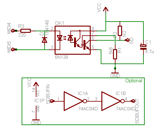
Schematic update January 16: The resistor values are changed to match Bill Byrne’s values.
The capacitor value is slightly increased as well. This is only a recommendation. 4.7 µF should be seen as a minimum value.
There’s also a new, optional, circuit which is an inverter circuit that works as a buffer. It should be more stable, however Bill’s device worked without it. Perhaps the resistor values need to be updated if you’re using the buffer. If you don’t want to use it, connect SD in the schematic to the cable leading to the SD pin on the cable. If you want to use it, connect SD in the schematic to SDBUFIN and connect SDBUFOUT to the SD pin. Ignore the weird “74AC04D” value in the schematic. The correct value is 74hc04 (Or a variant thereof)
To clear up any possible confusion about the R3 resistor: It should be a 220 Ohm, not a 200 kOhm resistor. 200 kOhm is far too big and will completely block the signal.
Part list:
| Pcs | What? | Value | Digikey# |
| 1 | Opto-coupler | 6N138 | 6N138QT-ND |
| 1 | Hex inverter | 74HC04 | — |
| 1 | Diode | 1N4148 | 1N4148FS-ND |
| 1 | Resistor | 220 Ohm | P220CACT-ND |
| 1 | Resistor | 1.2 kOhm | — |
| 1 | Resistor | 5.6 kOhm | — |
| 1 | Capacitor | 4.7 µF (Guideline) | — |
Update January 16: I’m dropping the Digiky numbers for new components.
A little disclaimer here. I haven’t yet built this circuit. (I only learned about it today, November 27, and I don’t have all the parts at hand) And I certainly haven’t bought anything from Digikey. But according to the best of my electronic knowledge, the circuit, as outlined above, should work just fine, and the Digikey links are my recommendations from what I can read in their descriptions. I do however not give any total guarantees that I’m right until I’ve built the circuit myself.
And likewise, until I get a chance to build it, you’ll have to interpret the schematic yourself. You might want to buy some prototype PCB’s, “Veroboard”.
November 28th, 2007 at 1:32 am
[...] to help the project, in terms of hardware and software development. So far, I’ve written a Pushpin hardware tutorial, which I will update as time goes [...]
November 28th, 2007 at 4:18 am
this is awesome..maybe someday we will try it..
thanks for the sharing :claphand:
November 28th, 2007 at 2:48 pm
I am not from ghana but nevertheless will try assembling a pushpin cable this w/end, thanks for the instructions.
November 28th, 2007 at 4:41 pm
I’ve ordered the parts to make this adaptor. I’ll try your way of doing it and see if it works.
November 28th, 2007 at 11:32 pm
Can you suggest an alternative to the 6N138?
November 28th, 2007 at 11:59 pm
6N136, 6N137, 6N138, 6N139 should all work, but I’m not totally certain they will. I’ve built one based on 6N136, but I can’t test it until I get home.
November 30th, 2007 at 5:41 am
Sweet nitro, way to be on top of things.
Ordering parts soon.
November 30th, 2007 at 7:00 am
Augh…
I feel for ya nitro.. I dug all the components out from lab and slapped them down on the proto-board, and was suprised to find the same, nada. I tried many different values, and some different configurations, about 10 tries in all, and nothing but a few random notes from the ARP.
I went back to internet archives, to catch som pictures of the oldschool interface that Shifty built:
http://www.gweep.net/~shifty/portfolio/pushpin/image/push004_clear.JPG
when I noticed a second the second 16 pin IC i got real confused? thought it was a MAX 232?
So, I emailed Shifty about this troubling development and he had this to say:
On Thu, Nov 29, 2007, Shifty said:
> yeah it’s a 74hcxxx. now it all makes sense.
> i wasn’t using the max232
> on Pushpin. heh.
>
> now i remember i tried it straight with just a 6n138 but couldn’t get the drive.
> That’s why I tried the cmos chip, as a driver. But I’m sure I didn’t try
> exactly nitro’s circuit.
> i found the GBC input was a bit dodgy. it never even liked straight
> voltage out of the
> driver. I had to put a stupid bias potentiometer in there somewhere
> to get it to work with a large number of MIDI interfaces! > I think it was connected to the darlington.
>
>
> someone please forward this mail to El Listo pweasey
> pwese?
there you have it, straigh from the designer himself, drive that signal baby!
I’ve ran out of Beer at the moment, so research has been put on hold until a near by corner store can be located and a mission for another 6-pack has been carried out.
Anyways, all this Pushpin business is the topic of my weekly youtubeism: http://www.youtube.com/the486kid
I’ll post my results there, when I have some.
L8RZzzzz
~486
December 3rd, 2007 at 3:38 am
Try replacing R1 with a 5k6 and R2 with a 1k2, and see if it’s any better. Also, make absolutely certain that R3 is not a 220k, which would guarantee that the circuit wouldn’t work!
And putting some sort of logic bugger also seems like a good idea. I’ll give it another try tomorrow and see if I can get it working this time.
April 12th, 2008 at 12:54 am
I’ve been waiting to see if someone would be able to figure out the issue with non-pushpin midi channels interfering with pushpin music data before jumping in.
nice work nitro2k01
May 2nd, 2008 at 9:30 am
hey nitro2k. any update on this? i want to build. does it work?
May 7th, 2008 at 10:08 am
please help meeeee !!! I dont underestand almost anything about making this synth i want to make a band here in Colombia that plays game boy sounds .. and I have watched videos on web about performing live, I want to know if this is the way they play music live, i mean with this kindda synth … sorry if i am bothering … anyway … thx for yout time
June 1st, 2008 at 4:30 pm
oh i’m so confused… are the instructions and the schematics now correct, updated and ready to build or is there still something wrong with it? i hope to be able to build it asap, i’m so excited about it….
June 2nd, 2008 at 7:29 am
Thanks for posting this circuit. I have got it working (with a 139 instead of a 138, which I don’t have lying around here). I did not need to use the double inverted signal output.
November 15th, 2008 at 9:03 pm
Hey Gameboy Genius, just wanted to mention something.
I’ve rebuilt this a couple times now, and I found some improvements.
I replaced the c1 with a 0.1 uf and it works better. I’m out of my depth here, not sure why, but it does. Also, I have not yet been able to get this going with 74HC04. But I’ve decided not to worry about that anymore.
Hope that folks find this helpful.
November 19th, 2008 at 7:42 pm
Thanks a lot Bill!
I think could be very usefull to know that the C1, 0.1 uf is a polarized one, not a polyester nor ceramic one.
December 1st, 2008 at 10:50 pm
Anybody have a suggestion on where to buy the 3rd party link cable?
December 1st, 2008 at 11:02 pm
…in the United States?
December 18th, 2008 at 2:06 am
mehhh im sooo lost with this. anyone got this thing working and able to give a full correct part list?
April 1st, 2009 at 9:18 pm
hi, thanx for putting this online! almost finished building this. just want to know.. does VCC connect to the 5V pin of the linkcable?
April 6th, 2009 at 4:54 pm
I hope changing part C1 in this schematic from a 4.7μF into a 0.1μF polarized capacitor, like Bill Byrne and Guiye Frayo state in the comments (i read it after getting the parts :S), wil make sending midi data to the gameboy more usefull.
All i get now the same random notes like the 486 kid.
April 6th, 2009 at 4:57 pm
I should clarify that as it stands today I haven’t been able to build a working PP interface. And I haven’t tried very hard after my initial attempt.
BTW, I edited your comment. This is a Wordpress blog, so it’s using HTML, not BBCode.
April 16th, 2009 at 7:49 pm
Hi Mates!
I hope this image can help you, I did my PushPin Interfase using this circuit and it works quiet nice.
http://img411.imageshack.us/img411/2991/pushpinmidiworks.jpg
Check out carefully the connections!!! It must be works fine if you have the right connections and your gameboy color port works…!!
cheers!
June 5th, 2009 at 10:13 pm
I had a working box awhile back with a 6n138 and a 74HC04. Took it apart to make something else.
Anyway i had posted some schems on the google pushpin forum. The one thing im interest in is has anyone fixed the problem with random notes when other channels are active.
Also i bought 15+ connector cables that i could put up on ebay if needed.
September 2nd, 2009 at 11:54 am
Dont anybody know if this will work with gba sp? thanks
September 2nd, 2009 at 11:57 am
It will not. Only, only GBC will work.
January 20th, 2010 at 10:33 am
Hey nitro, I know this is outdated, but i want to try to build this. I have the exact same link cable; which colors stands for 5 V, SD and Gnd. ?