![You suck at protoshop. No, you [i]really[/i] oo.](http://blog.gg8.se/images/you-suck-at-photoshop-you-really-do-your-awful.png)


How to patch your DMG to use a biverted palette
November 23rd, 2009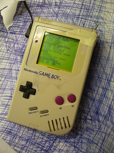
Inverted:
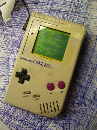
(Please excuse the shabby look, but that is my guinea pig Gameboy that I use for experimentation.)
I’ve already explained how you can invert the monochrome palette in LSDj which is useful if you have a DMG backlight with an inverted polarizer film on your DMG. But what if you want to use a normal palette for other software or games?
Modding the ROM of the game or program you want to invert the palette for is an option, but it may not be practical. Fear not however, the protocol that the DMG is using to transfer data from its all-in-one chip to the LCD is strikingly simple, and can easily be inverted with a 74hc logic circuit of your choice, a so-called biversion.
First let’s have a look at how the protocol works.
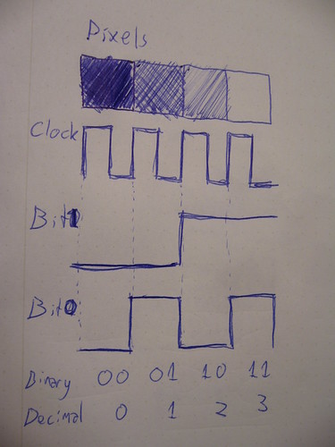
For the sake of this tutorial there are three important pins to keep track of. Data bit 0, data bit 1 and clock. At every rising edge clock edge (when the clock line changes from 0V to +5V) the current state of the data lines is recorded, and the corresponding pixel value is drawn to the currently active pixel on the LCD. This keeps goes until the whole screen is filled with an image. And then again and again. (Ok, there are more aspects to it, like so called “blanking” but that’s not relevant for this discussion)
So what you need to do is change the values of the data lines in such a way that black becomes white, light gray becomes dark gray and so on. The way to do this is by simply inverting the two data bits. There are (at least) two possible ways to do this.
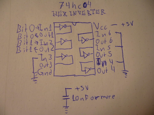
One way is to use a simple inverter like 74hc04, where you connect the data bits to the appropriate input and outputs. Also note two things abut the schematic:
1) I have connected all unused input to ground. (Unused outputs should remain unconnected)
2) I’ve added a bypass capacitor between Gnd and +5V
Neither one of these things are strictly necessary but they are good practice, and may help reduce interference to the signal if that would be a problem.
And obviously you can use any pair of inputs and outputs on the chip.
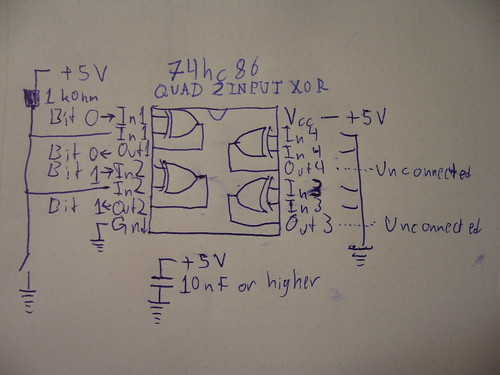
The other way of doing it, which is what I did for my prototype, is to use xor gates. (74hc86) The advantage of that method is that you can switch between the modes easily with a switch. If you xor a bit value with 0, you get back the same bit value. If you instead xor the bit value with 1, you get back the inverted value. So in this configuration, I’ve connected a weak pullup resistor, which sets one of the inputs to 1 by default, meaning the image is inverted by default. However, if those inputs are shorted to ground, the xor operation returns the original data and the picture is again unaffected.
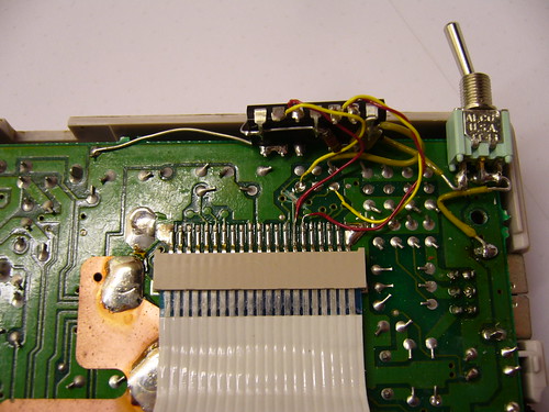
So, how does one actually connect the inverter? You need to cut the copper trace where the data and solder the input and outputs on each side of the cut.
This is what my prototype circuit looks like. I’ve connected the inputs of the inverter to the appropriate holes that are already available in the motherboard, but filled with solder.
A sidenote on these holes: They were most probably placed there to enable connection to the WideBoy unit, which was an official Nintendo development kit that allowed the screen image of a Gameboy to be displayed on a TV with the help of a NES.
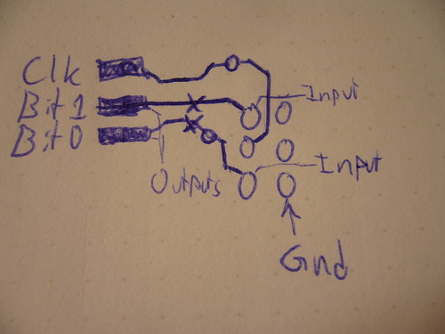
At any rate they come in handy now. The above diagram show you where to tap the input signals, where to cut the traces, and where to solder the output wires. When cutting the traces make sure you cut them properly, or you’ll have a conflict. Do not cut the Clk trace.
All three holes shown to the right in the diagram are connected to Gnd.
Last but not least, a video of the thing in action:
So… Tell me what you think. Is this information useful? Anything unclear? Is my English to quirky and corny? Anyone interested in buying kits for this thing?
The terms “biversion” and “bivert” were later coined for this mod by Bibin.
November 23rd, 2009 at 11:03 am
you are a wizard.
November 23rd, 2009 at 2:14 pm
So useful. I’ll put this into action soon. Where should I buy a 74hc86?
November 23rd, 2009 at 7:52 pm
Just tried it with the schmitt gates and it works perfectly, but i want it on a switch so i am going to keep trying.
amazing work keep it up
November 23rd, 2009 at 11:53 pm
Sweet! I’d order a kit. It’ll be nice to have a DMG inverted twice without messing with each ROM.
November 24th, 2009 at 12:25 am
Bibin: I don’t know… There’s a student lab at my university where companies have donated circuits through out the years. We have a drawer full of just different 74hc circuits. I suggest you settle for the 74hc04 version, since 74hc04 is way easier to find than 74hc86. As NeX said btw, a schmitt triggered gate will work too, 74hc14. They are the same pinout, and equivalent when used like this. In fact, if I do a kit, I’ll probably go for 74hc04, since I couldn’t find any surface mount 74hc86’s.
If you really want a switch, you could use a 74hc04 + a DPDT switch to choose between the two.
November 24th, 2009 at 1:04 am
[...] inverted Palette Mod: http://blog.gg8.se/wordpress/2009/11/23/how-to-patch-your-dmg-to-use-an-inverted-palette/ [...]
November 26th, 2009 at 9:14 pm
Amazing work. I love it!
November 30th, 2009 at 2:59 pm
Just tried it with the 74hc86 chip and again works perfectly! i ordered a minimum order of 4 chips, so i think a lot of other gameboys are going to get this mod.
December 6th, 2009 at 9:20 am
[...] How to patch your DMG to use an inverted palette [...]
December 6th, 2009 at 4:50 pm
[...] below: The left picture is a Nonfinite backlight with an inverted polarizer. (And of course a 74hc04 screen inverter to uninvert the image) It has white LEDs which is atcually a bad idea for use with a monochrome [...]
October 7th, 2011 at 4:55 pm
[...] also known as bivert mode using a logic circuit chip 74HC* and also has been suggested by bibin and nitro2k01 (they has easier tutorial on how to install Hex Chip. Different kit but it is basically the same). [...]
March 4th, 2012 at 10:56 am
[...] are mostly redundant now because the standard method of installing a backlight these days is with a biversion, i.e. a hardware [...]
March 4th, 2012 at 6:05 pm
[...] Die Bitinvertierung hatte ich jetzt auch noch nicht eingebaut, wegen Schalter und weil ich mir die Anleitung nochmal anschauen wollte [...]
March 8th, 2012 at 2:17 pm
This video literally just gave me a hard-on.
March 21st, 2012 at 11:17 am
Hey so do i just need to add a switch to the ground to make it reversable?
March 21st, 2012 at 11:42 am
You do need the pullup resistor to +5V as well, but yes. (The value of this resistor can safely be increased to 10 kohms or more for a slightly lower power consumption.) This assumes you’re using the 74hc86 (quad xor chip). If you just want to invert the screen without a switch, use the 74hc04 chip instead.
February 9th, 2013 at 11:42 am
Why not just invert the one clock signal instead of inverting two bit signals? is there anything wrong about that? or will it have issues cause it’s now 180° phase?
February 9th, 2013 at 11:51 am
Tyler: The drawing just shows what the signal would look like if four pixels with the four possible values would be clocked out consecutively. All the clock signal does is tell the LCD when there’s new pixel data on the data lines. Inverting the clock would just make this happen half a clock later, and the most you could possibly achieve with this is to shift the whole LCD image one pixel to the left.
February 9th, 2013 at 12:01 pm
Oh… silly me. I’m not too keen on how things operate when it comes to electronics. I know very little from building lunetta synths and modding a c64 for use with MSSIAH. As you rightly assumed, I was basing this off your drawing. thanks for the clarification. One quick thing while it’s on my mind, I was reading the comments on Michael Moffitt’s tutorial page about this mod and there are two folks that claim they broke their gameboys trying this mod. Is this mod honestly safe when installed properly? I have confidence in my soldering, but these comments have made me cautions.
February 9th, 2013 at 12:19 pm
I’ve never experienced this. The only non-trivial way I could see this happening if the soldering was done flawlessly, is if the traces were not properly cut so that the input and output of the inverter chip were shorted. This could cause the inverter to start oscillating really quickly, which wouldn’t be good for the LCD, or the DMG CPU for that matter. So test with a multimeter in continuity mode that the trace is really broken. Then scratch some more.
Of course, the usual caution applies. Make sure the chip is correctly oriented and doesn’t press against something in such a way that it causes a short. Also make sure that all connections are good before powering up.
And while we’re at it, never connect or disconnect the ribbon cable while the Gameboy is powered on. It’s very easy to accidentally connect the LCD drive voltage (-19V) to one of the button inputs, which will kill the left and B buttons.
February 9th, 2013 at 12:31 pm
Well thats a relief. I have a DMG coming in the mail I’m going to be modding (my first gameboy mod) and I’m making a check list of the things I will be installing. The obvious prosound connections/backlight, and now this inverter. I just found this mod not 10 minutes ago so I’m going to opt for an inverted polarized backlight and this mod to get some super contrast going. Thanks for the very helpful info. I can’t tell you how much I appreciate it. I need all the help I can get sometimes =P ciao for now
February 9th, 2013 at 12:43 pm
However, note that if you’re primarily going to use the Gameboy for LSDj, there’s a builtin option to invert the color scheme in software to match the rotated LCD layer, so you don’t need the hardware mod described in this post. You can also do this yourself with limited success with some games, as described in an earlier post. (Linked in this post.)
And obviously, be careful when peeling the layer off the LCD.
March 13th, 2014 at 1:56 pm
hey im very glad for your work,
im tried to invert with a gd74hc04 chip like you explain but i got all the time flickering contrast ore some stribes
what did i wrong . could you do some drawing ore somthing to get the problem fixed !
thanks for your help,,,,
September 15th, 2016 at 11:34 pm
Hi nitro2k01,
Thanks for your work, it’s an interesting blog.
I want to use an 74HC04 inverter but actually I don’t know if Vcc should be 5V or 3.3V, what should I take into account? or should it always be with 5V?
Thanks, best regards.
November 15th, 2016 at 1:56 am
Vcc should be what it is in the rest of the system. In this case 5V. You should not add a 3.3V regulator or anything like that.