![You suck at protoshop. No, you [i]really[/i] oo.](http://blog.gg8.se/images/you-suck-at-photoshop-you-really-do-your-awful.png)


Marty Kraham, aka TV Death Squad is the worst chiptune thief ever
September 19th, 2009Originally published 2009-07-19 and later removed. Republished in 2016 following the news that Marty Kraham has been sentenced to 5 years in prison for having unprotected sex with multiple people while lying about being HIV and Hep C positive, which he was diagnosed with as early as 2007. If you have had sex with Marty Kraham, you should get tested for HIV and Hep C if you haven’t already.
Sources: 2014 chipmusic.org thread, 2016 chipmusic.org thread, News9 news story, Koco news story.
The buzz in the 8-bit community the last 24 hours has been Marty Kraham from Oklahoma, who promotes himself as a chiptune artist under the name of TV Death Squad, but whose whole repertoire seems to consist solely of material from other artists. Here’s a recap of the discussion about him. What started as any Myspace kid uploading Random (Note, the artist known as Random) songs, continued as a successful search for other songs he might’ve plagiarized and ended up as a fruitless attempt to find something about this guy that isn’t fake.
Let’s go through this guy’s merit list.
His Myspace, now empty, contained a number of songs, most jacked directly from 8bitpeoples releases. Here’s a list made by Sycamore Drive. Likewise, his Youtube account no longer exists.
April 16 or thereabouts at Electronic Game Expo 2009, he is “playing live”. Only problem is that the track playing in the background is “Eight Vic Day” by Ten And Tracer from an EP called Dark Before Dawn, released in 2002 on netlabel 8bitpeoples. Download here. The only people playing live in that video are the kids who are playing around with Marty’s effect/noise boxes.
Camera: John Wells
see comments for fraud
These videos were sent to the local production company Above the Bar Productions for editing, about the same time and quite possibly from the same event. The music plagiarized in the first video is “Croatian Love” by artist Mesu Kasumai and the second one is “OK, So The Ninjas Went To Space…,” from Psilodump’s EP Mutiny Of The Robots.
It should be noted that Above the Bar responded quickly and condemned his actions strongly. They’re just a production company that happened to get this tape sent to them for editing.
These two were recorded at Game Core Gaming Convention on September 12. In the first video he makes the mistake of plagiarizing one of the most plagiarized songs in the modern history of chiptune, Random’s Sitge’s Savepoint from Bad Joke EP. His only contribution is to add some very crappy effects on top of the song with the Kaoss Pad in his keytar. He claims that he played it only as a demo to the visuals in his Kaoss Pad, which is a lame excuse since it doesn’t explain why he danced like a wild child, doesn’t explain why he pretended to play on the keyboard and definitely doesn’t explain why he uploaded the uploaded the song to his Myspace and absolutely positively doesn’t explain why there doesn’t seem to be any original material from this guy at all.
In the second video at about 0:35, notive how he picks up his Gameboy, without an audio cable running into it, rocks out for about ten seconds, then probably realizes his mistake and puts it back to rock out with the keytar instead.
The problem here is that people don’t realize that just because people release their music for people to listen to it for free doesn’t mean the music is open for reappropriation. All music on 8bitpeoples is released under a Creative Commons license which permits free listening and redistribution, but (Depending on license flavor) but enforces attribution and restricts the production of derivative works as well as commercial exploitation by 3rd parties.
What is missing (Unless someone downloaded a copy they can mirror) is the video where he’s selling his Prosound DMG. He demos it by playing a SID tune and pretends (badly) to push the buttons in sync with the music. Just as badly as he pretends to play his keytar in those two videos.

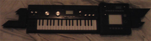
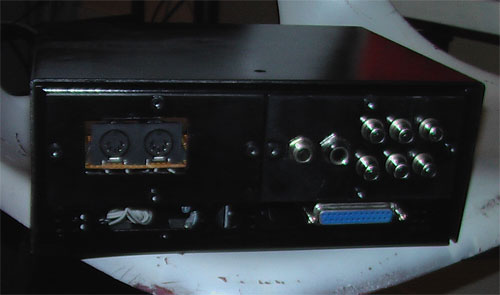
What about that keytar btw… That’s the only cool thing about that guy, he ordered a custom made keytar from circuitbender Cosmic Blooper. It consists of a Microkorg XL and a Kaoss Pad on the side.
According to CB’s blog post Marty was in a hurry to get it. My guess is he wanted something to hold in his hands during his big show at GCGC.
So what else…?

LSDj shirts for sale… Hmmm…

Look whose name we have here! Yep, it’s marty again. While I’m sure Johan doesn’t have too much against people selling LSDj shirts, it’s mifts perfectly into Marty’s image as a poser and plagiarist.
(Go look for yourself before while the shop is still there)
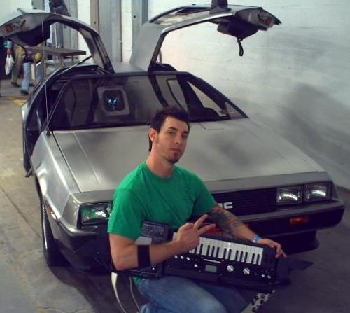
And this is how he looks with his custom made keytar. Stereotypically, he looks more like a “tough guy” than a chiptuner. Just look at that pose, priceless!
But there’s one piece missing. When I googled him, I found his Twitter.

His only two tweets are right after each other on April 20, the unofficial stoner day. It’s not a stretch to think that he was high when writing those. (Notice how he writes 4:20 as a time of day, not a date) That’s when I start to draw conclusions about the guy. Probably a bit of a stoner. Basement dweller who lived a little too long with his parents and got a little too much for free. A guy with too much aspiration and dreams of fame, and too little inspiration and skill to match up. A guy who can afford to buy a bunch of effect and noise boxes and video game consoles but doesn’t have a clue how to use them for music, but still don’t want make a fool out of himself in front of his family, friends and fans.
At that point I don’t know if I’m supposed to hate him or feel sorry for him.
Update:
Here’s a conversation between Random and Marty. Judge for yourself.
TV Death Squad
random,ive had the whole world pissed off.. FIRST off i am a VJ, not a musician… i specialize in visuals, i am no different than an 8 bit dj with vocals… i have done nothing but help promote how bad ass your music is and even do visuals over it.. EVERYONE at the event knew who wrote every song, thats why i had the setlist with the artists names !! i can understand why your pissed, but it sincerely is not what you think.. anyways, if you or random or wik are upset ill remove any promo for you guys.. let me know
Random
Hi,I have a hard time believing you because:
1. You are clearly making some sounds in the beginning of this video: http://www.youtube.com/watch?v=PRCqzJEA0yw. VJs don’t make sounds as far as I know.2. You have a Game Boy on stage, and you pretend to play with it. Why would you do that if you were a VJ only? You are obviously pretending to play the music.
3. You are listed as a live performing band on the Game Core website (http://www.gamecorecon.com/events.html)
4. You say everyone at the even knew what music you were playing, but some one from the Game Core crew has commented on my website (http://randomizer.se/2009/09/another-music-theft/) saying “If we knew we would not have let him play that is BS.” - and if the organizers didn’t know, I simply don’t believe you when you say “EVERYONE at the event knew who wrote every song”.
5. You had my music uploaded on your myspace profile, and you renamed the tune. So what’s this bullshit about “setlist with the artists names”? Again, if you were a VJ, why would you do that?
6. None of the other videos I’ve found on Youtube or Vimeo have any information of what music is actually played. It really looks like you’re pretending to be the artist in all of them, no matter how I look at it.
To sum it up: things don’t look so good for you in this case. If you still have anything to say in your defence, go ahead, but I doubt it will do anything but make you look even more like a liar.
It’s good that you’ve removed your myspace profile and the videos on youtube, though. “Thanks”.
TV Death Squad
i feel shitty about the whole thing. i took down everything i possibly could of, and have said im sorry to everyone on the list. i didnt intend for
anyone to get this upset. again, i am really really fucking sorry that the the videos were misleading. to answer your ?, the entrancer does both audio
and visuals, that gameboy is a “glitch box”, there was a setlist there at gc. and i didnt rename your song to be a douche, i thought it was called strange place or something.. anyways i have done what i can to try to fix a shitty situation. again im sorry
SGB bootstrap ROM dumped by Costis
September 19th, 2009About 6 years ago Neviksti managed to dump the internal 256 byte bootstrap ROM used byt the DMG (First model Game Boy) to scroll down Nintendo logo, play the po-ling sound and confirm that the cartridge header is in order before allowing the cartridge to be executed. He did so by opening up the epoxy covering the chip and reading out the memory visually bit by bit though a microscope. This was groundbreaking because there was no ordinary way to read the ROM as it was shut off by an internal register after bootup.
Just the other day, costis dumped the corresponding ROM image from the SGB (Supe Game Boy) with a slighlty different method, namely clock glitching. Costis’ method is using an FPGA to run the system clock normally up until the point where the protection register is to be written. At that point the clock frequency is increased to such a fast speed that the write is ignored by the protection register and the execution continues into the user code, which then dumps the 256 byte big code. The operation was surprisingly painless according to costis himself. Next up is the GBC which is believed to have a bootstrap ROM bigger than 256 since its startup procedure is much more advanced, distinguishing between GBC and DMG, and letting the user choose palettes for monochrome games.
For more info, see costis’ SGB hack page.
Gijs’ Gameboy Camera Animation Converter
September 17th, 2009
GB Camera Sav -> GIF animation converter by Gijs Gieskes
mGB with extended MIDI channel support
September 16th, 2009 I’ve had the privilege of getting access to trash80’s mGB code, which of course has given me the opportunity to make improvements. My first improvement is to add support for extended MIDI channels. (1-5,6-10 or 11-15 depending on which ROM you’re using.) This is useful for people who want to use mGB on the same MIDI output as MIDINES, other synths or perhaps use 3 copies of mGB simultaneously with one Arduinoboy. (With three link cable plugs).
In a future hacked version I’ll include the ability to choose which channels to use in the program, and also make mGB play nicer with LSDj. (Not corrupting savs and so on)
GBC Prosound idea
September 13th, 2009Sorry for the blog hiatus during and after my vacation. Before the vacation I came up with a new way of routing the audio cable that I don’t think I’ve seen before. (Feel free to correct me.) Most GBC prosound mods I’ve seen are based in the idea of routing the cable downwards to the bottom of the board.
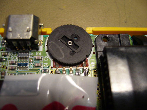
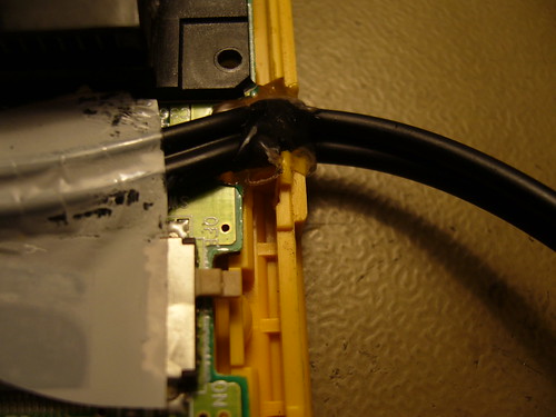
My idea on the other hand is based on connecting the audio wires to the potentiometer as usual, then routing the cable over the PCB, so that it sits below the cartridge when the GBC is reassembled. The cable would then exit through a hole on the right side of the of unit.
The trick however, to make this mod work, is to cut away a piece of the PCB to make room for the cable. The copper trace that is affected, is relatively wide, so there’s some margin. However, it’s for the power supply, so there’s a small risk that you might need to compensate for the loss in size be adding an extra wire. I haven’t had any problems with this yet, but I guess this would depend on how big a piece of the board you cut away. The only slight problem I had was that the cable just barely fit into the space when reassembling the GBC. But it seems to adjusted itself and it now works beautifully.
Pics:
The wires soldered to the potentiometer. I soldered the wires pre-pot to always get maximum volume and minimum impedance. (I’ll always be connecting it to a mixer anyway.)
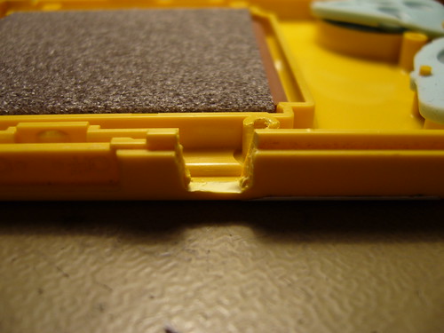
The notch in the PCB (Front) - modded vs unmodded board
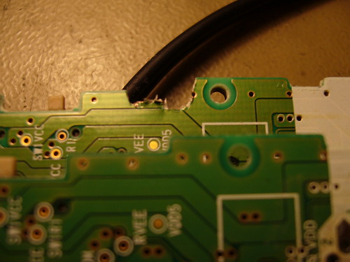
The notch in the PCB (back)
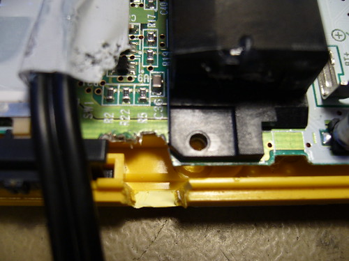
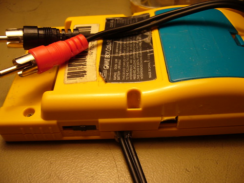
The hole where the cable exits
Zoomed out

Some hot glue to fix the cable
The final product (Reassembled)
What thinks?
LittleFM beta testers needed
August 11th, 2009LittleFM is an alternative file manager for LSDj, with its main feature being the ability to back up song data to the flash memory of Bleepblop cartridges for bigger and more solid storage. (It currently isn’t confirmed to work on any other cartridge.)
Info and first public version here.
What is LittleFM?
August 5th, 2009I’m right now working on a project called LittleFM. It’s a software project for Gameboy, written completely in assembly language. But can you figure out what it is? Post your thoughts and guesses. (Don’t reveal the secret if I already told you…)
Fixing Gameboy-powered Arduinoboy MIDI glitches
July 26th, 2009I recently had a little problem when building my Arduinoboy. The Arduinoboy did appear to work, but it was glitchy. Some MIDI notes were ignored or gave strange results, and sync didn’t appear to work at all. I sat down and compared trash80’s schematic to other MIDI 6n138 schematics and I noticed something: There was not resistor between pin 7 and ground in trash80’s schematic, which is is otherwise common in MIDI optocoupler circuits.
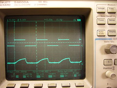
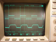
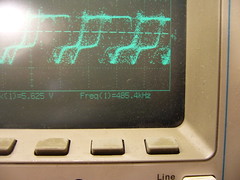
Left: Before, Right: After. Upper waveform: Test signal source, Lower waveform: Opto-coupler output. Both powered by the Gameboy.
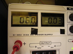
So I set up a prototype circuit with a test signal of 32 kHz to see if I could trace the problem. It turned out that the problem only happens when you power the Arduinoboy from the Gameboy. When powering it with +5V it worked alright and the oscilloscope output looked ok. However when powering it from the Gameboy, the combined losses from the lower output voltage from the Gameboy (The DC/DC only outputs 4.8 V as shown in the previous post) the protection diode at the Gameboy’s link port and trash80’s way of driving the 6n138 resulted in a source voltage of 4V for the 6n138 which made the rise time way to high, as you can see in the left picture.
Adding a 4.7k resistor between pin 7 of the 6n138 and ground decreased the rise time enough to make the circuit work flawlessly. So if you’re having problems with a Gameboy-powered Arduinoboy, try this. Fixed version of trash80’s schematic provided below.
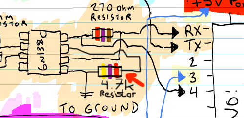
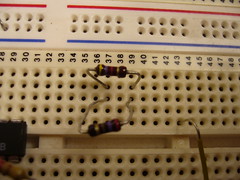
And finally a word of caution. Don’t confuse the 4.7k resistor with the 270 Ohm resistor. A 270 Ohm resistor with a 5% mark (gold strip) can look confusingly similar to a 4.7k resistor. Can you tell the difference below?
Testing Gameboy input voltage ranges
July 22nd, 2009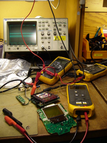
Introduction
Recently there was a discussion about on 8bc about a new way of backlighting DMG’s. Bonewire’s backlighting method replaces the batteries with two 9V batteries. This raised the discussion of whether you could power the Gameboy directly with a 9V battery, or whether it would explode/otherwise fail.
I wrote a post about the inner workings of the regulator and promised to come back with some more measurements of the performance of the regulator at different voltage levels.
To clear possible confusion: One important aspect of the regulator is that it’s a switching type regulator which is using a feedback mechanism to keep the voltage steady. Because of its design it’s able to do so whether the input voltage is lower or higher than the target voltage of about +5V. Thus, the input voltage may vary, while the output voltage stays (relatively) constant. This is useful for battery operation since the batteries can used as long as they are able to give enough current, whether or not their voltage is low. Switching power regulators, in general, also have a power conversion ratio: Little energy is lost in the conversion. (As opposed to a linear regulator, like the 7805 & co, which are guranteed to wate at least a certain amount of energy as heat)
Test Conditions
The goal of the test is to benchmark the input voltage range at which a Gameboy power supply would work at. The test subject was a DMG-CPU-7 revision motherboard with a DC CONV DMG converter. (There are at least two versions of the regulator board; the other one is marked DC CONV 2 DMG and has a couple more components on it.)
I used a xzakox type flash cartridge loaded with LSDj, playing a melody, with power save set to off.
Here a few notes on the measured values:
- Vin was adjusted in steps of 0.5 V and 1.0 V. The value is accurate to ±10 mV for all it matters
- Vout was measured with a multimeter and is accurate.
- Iin is the input current as displayed by the power supply unit, and is fairly inaccurate. (It only shows the general tendency)
- DC/DC control RMS/f This value is also a bit hit and miss. I tried to read out the frequency which the DC/DC converter was working at, from the oscilloscope, to the best of my ability. This value fluctuated a lot, and is also just there to give a general picture of the freqeuncy. At the lower values the oscilloscope was unable to detect the frequency at all.
That is what the cryptic RMS voltage is there for. It should give a rough idea of the duty cycle of the control wave. - Notes These are my observations for some of the voltages.
Test Data
| Vin (V) | IIn (A) | Vout (V) | DC/DC control RMS/f | Notes |
| 1.5 | 0.15 | 4.79 | ~2.1V | Prone to crash, no sound, DC/DC buzz on startup |
| 2.0 | 0.12 | 4.82 | ~2.4V | No sound |
| 2.5 | 0.11 | 4.84 | ~2.7V | Display will lose data when playing sound |
| 3.0 | 0.05 | 4.87 | ~3.0V/~260kHz | Appears to work normally, possibly a bit glitchy/unstable |
| 3.5 | 0.06 | 4.86 | ~3.2V | |
| 4.0 | 0.05 | 4.87 | ~3.5V/~300kHz | Fully normal operation |
| 5.0 | 0.05 | 4.88 | ~3.5V/~320kHz | |
| 6.0 | 0.04 | 4.89 | ~3.6V/~390kHz | |
| 7.0 | 0.04 | 4.89 | ~3.6V/~415kHz | |
| 8.0 | 0.04 | 4.90 | ~3.6V/~460kHz | |
| 9.0 | 0.03 | 4.90 | ~3.7V/~500kHz | |
| 10.0 | 0.03 | 4.90 | ~3.7V/~510kHz | |
| 11.0 | 0.03 | 4.89 | ~3.0V/~700kHz?? | |
| 12.0 | 0.03 | 4.89 | ~2.6V/??? |
Observations and conclusions
Low voltage operation
The first interesting observation is the behavior in the low end of the voltage spectrum. The regulator could manage to keep the CPU alive at an input voltage as low as 1.5V. However, at that voltage there were significant power losses in the conversion, sound wouldn’t work and the Gameboy would crash easily.
At the transition 2.5V->3V you can see a significant change in input current, and I also noticed a change in behavior on the oscilloscope. I’d define 3V as the absolute minimum voltage that the regulator board can handle stable.
Sidenote: This possibly opens the door for using a Li-Ion battery for powering a DMG.
Normal voltage operation
At 4.0 V the Gameboy is definitely operating normally. As the input voltage is increased, the switching frequency is increased of the regulator is increased. No abnormal behavior. At no point during the testing did I notice and excessive heat production in the regulator circuit.
Above-normal voltage operation
4 AA batteries can not reasonably produce voltages higher than 7 V, so anything above that could be seen as outside the standard range of operation.
So what are the effects of voltages above 7 V? The regulator itself seems to handle it fairly well. And the +5V output only fluctuates 100 mV, so the CPU won’t be affected. However, while the +5V is regulated, the -18V line used by the LCD is not directly regulated, but instead current limited by a 510 Ohm resistor.
It is possible that the increased input voltage will also increase the LCD voltage in such a way that it damages the LCD. The Gameboy I used for testing already had a slightly damaged display, but when I was done wih the testing its display was more or less completely broken (would turn off or glitch out within seconds after turning on the power, regardless of input voltage)
I tried feeding my known good Gameboy with 9V for a few minutes, with a moderate contrast setting, without any problems. However, it’s possible that the extreme positions of the contrast dial will slowly destroy the LCD, when the input voltage is >7 V. If so, it could probably be fixed by changing the control voltage range for the contrast dial.
I’ll have to investigate that further, but my preliminary conclusion is that you can feed the Gameboy with a 9V battery without problems.
Soup is better than twitter
July 18th, 2009Or at least I think so. Or maybe I just have something against Twitter. Anyway, check my soup, and maybe subscribe to my RSS feed there too. I’ll be posting little links and stuff there, probably more often than I post stuff here.