![You suck at protoshop. No, you [i]really[/i] oo.](http://blog.gg8.se/images/you-suck-at-photoshop-you-really-do-your-awful.png)


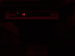
Studio monitors, M-Audio BX5a
December 25th, 2008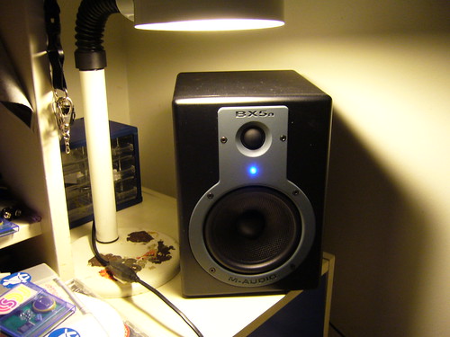
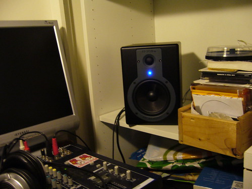
This is my Christmas present for myself, a pair of studio monitors. (That’s music-ish for a pair of reference speakers used to monitor the sound in case you didn’t know ![]() ) They’re a budget model, but I got them for half the price because the store was buying mark II of the same model and had to get rid of the old ones. I didn’t get around unpacking them until pretty late in the night, so I haven’t been able to test them properly yet. (Bass turned down on the mixer, low volume output - don’t want to upset the neighbours) But as far as I can tell they sound ok, absolutely better than anything I owned before. The overall sound image is balanced, but they lack in the sub department. Which is only natural since the job of studio monitors is to be a reference to work by when producing and mastering sound, not to provide a booming bass for listening experience. And they sound good even on low volume levels. They’re also compact, which fits my lifestyle well.
) They’re a budget model, but I got them for half the price because the store was buying mark II of the same model and had to get rid of the old ones. I didn’t get around unpacking them until pretty late in the night, so I haven’t been able to test them properly yet. (Bass turned down on the mixer, low volume output - don’t want to upset the neighbours) But as far as I can tell they sound ok, absolutely better than anything I owned before. The overall sound image is balanced, but they lack in the sub department. Which is only natural since the job of studio monitors is to be a reference to work by when producing and mastering sound, not to provide a booming bass for listening experience. And they sound good even on low volume levels. They’re also compact, which fits my lifestyle well.
So yeah, at any rate I’m satisfied since this is a step up for me.
Perler Bead Christmas Crib
December 25th, 2008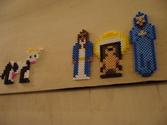
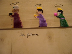
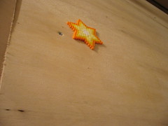
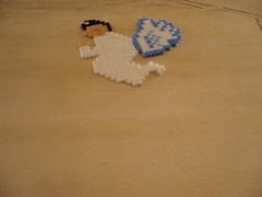

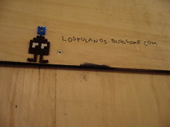
This is the Christmas myth told in Perler Beads. Found in the tunnel under Årstabron, near Tantolunden in Stockholm, Sweden. Apparently made by Los Fulanos.
Perler Beads are getting more popular, and so is pixel art. Coincidence? I think not!
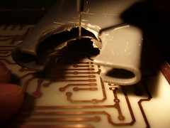
Frankenstein’s Headphones
December 22nd, 2008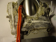
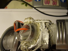
When I originally got these from a friend, they were physically intact, but one wire was broken due to excessive use. So he donated them to me so i could fix them and use them (I didn’t have any decent headphones at the time.) I fixed them by replacing the internal wires with thick, durable copper wires that I placed externally. That’s the orange wires that run into the earpiece.
Everything was fine and dandy for a few months until a crack in the plastic so big that the left earpiece fell off. My first temporary solution was to use tape to keep everything together. It worked, but it wouldn’t sit tight.
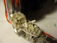
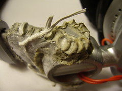
Time for the next fix. First I tried super glue which worked at first but soon fell apart. So I proceeded to welding the plastic together with a soldering iron. I also reinforced the plastic with some steel wire. The result is that the plastic is welded into one solid piece, which will hopefully last for a long time.
And it also looks sort of dirty. Since these headphones could’ve died 6 months ago, but I revived them at least twice, I hereby officially dub them “Frankenstein’s Headphones”. After all, the membranes were, and still are working perfectly, so why throw the headphones for something as silly as a broken cable or some cracked plastic?
Tomorrow though, i’ll be getting something better. You’ll see.
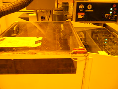
PCB Manufacturing at my university (Pictures)
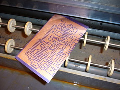
December 19th, 2008So I etched a PCB at my university today, and i thought I’d share some pictures. Today’s PCB is an XR-2206 Based Voltage Controlled Oscillator, a rad oscillator synth module.
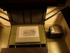
The manufacturing process involves several transfers: Paper -> Photographic film -> Photoresist -> Copper. Let’s begin with a picture of three of the steps, the printed paper, the film and the finished PCB.
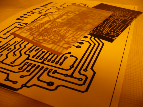
So the first thing I have to do is print the layout on paper. It needs to be printed with high contrast and dense blackness to transfer well to the photographic film. For this PCB I chose to do the transfer double sized to increase the contrast, but you can transfer it with a 1:1 size source printout. (Or anything between)
 The next step is to expose the photographic film. This is done with a device consisting of a glass plate under which you put the original, and a lid under which you put the film. Both the glass and the lid have vacuum suction to keep the paper and film in place.
When you press a button, two light sources are turned on to expose the film. The light is reflected against the source material through a lens, and onto the film. The film is, as far as I know standard black and white photographic film. In other words, this device is a giant camera.
The next step is to develop the film. This is done by putting the film first in a “developer” fluid to make the image visible, and then in a “fixer” fluid to protect the film from light. Until the film has been completely developed, the photo room must be lit strictly using a faint red light to avoid exposing the film by accident.

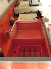
 Next up is transferring the image on the film to the photoresist on the board. Unfortunately I forgot to take a picture of this step, but it’s done by exposing the photoresist to UV light through the film. The photoresist will be weakened in all areas exposed to the UV light. The weakened areas will then be etched away using a CaCO3 (Calcium carbonate) solution in the first etching machine. The result is that the copper is exposed at those parts. (Left picture) And then I put it through the second etching machine, containing iron chloride, which will etch away the exposed copper areas. (Right picture)

Almost done. The last step is to put the board into a stripper fluid (NaOH, Sodium hydroxide) to remove the remaining photoresist.
After drilling the holes the PCB is ready to be equipped with components.
Cadsoft Eagle libraries for synth makers
December 12th, 2008When looking for an Eagle library containing the transconductance op amp CA3080 for a little thing i’m building, I found synthdiy.lbr which is library containing a number of useful chip layouts. Eg, 2SA798, 2SA1349, 2SC1583, 2SC3381, AD633, CA3046, CA3080, CA3280, IT120, LM394, LM2931, LM4040, LM13600, LM13700, LS318, LT1013,
PAN9MMPOT, TLV5618A.
Might be useful to someone.
Originality Award Monthly November: burnkit2600
December 11th, 2008The November winner of Nonfinite’s Originality Award Monthly is Burnkit2600 for their album This Is The Sound. Burnkit2600 are also avid circuit benders. For example, me and Veqtor are planning to bend our Alesis HR-16 after seeing his HR-16 info page.
Congratulations to a well deserved prize!
Anime Wallpapers (Asuka Langley from Evangelion)
December 11th, 2008
Thanks to this picture by Ignatz I found this wallpaper by this artist. (<- Click that link for more)
I usually use a plain black background instead of wallpapers. (Opera is covering the screen most of the times anyway) But I felt that I needed a change, so I’m using this wallpaper instead. ![]()
Fun with NYC video billboards
December 10th, 2008Can video billboards normally displaying advertising be transformed into art? Three artists agree they can. These billboards are placed allover NYC at subway stations, and apart from spreading commercial messages, they make perfect light sources for unauthorized art.
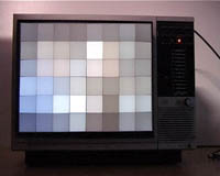
The Pixelator is IMO the most innovative of the three. By using a grid of walls and diffusion gel, you get a live pixel effect on any TV screen.

Light criticism by Anti-Advertising Agency and Graffiti Research Lab is using the billboards as a light source by covering it with a board with message cut out. The messages are anti-commercial, like NYC’s TRUE GRAFFITI PROBLEM, GRAFFITI and GRAFFITI = ADVERTISING
You should check out the rest of Graffiti Research Lab’s projects as well.

The idea of the The Abstractor is to mask out everything shown on the screen but a thin horizontal line, and so make an abstract subset of the TV image.
Click on any of these links for a better description and instructions how to build that project. Each link also contains videos of the project in action.
Through: Project October
New song draft: Knarkkatt
December 9th, 2008Thought I’d post this. It’s the first draft of a sort of chip+ambient song I’m working on.
The chip sounds are pretty melodic, described by some as “shimmering” Actually the melody is from “Belsebub Till Frukost” which can be heard on my myspace. (Skip to about 3 minutes into the song)
The pads are made with Reaktor and are somewhat detuned and played to color the chords of the chip melody. The result is a really moody feeling.
Sorry for building a suspense and then ending abruptly, but it’ll make you enjoy it even more when it’s finished. ![]()
Download Knarkkatt (Draft 1)
ModularDuino - An Arduino Based Modular Synthesizer Concept
December 9th, 2008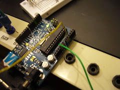
General Description
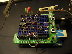
The idea of using my Arduino for modular synth utilities started out as a crazy idea that I’m now starting to seriously like. The pictures above shows my first design, an oscillator. (I have plans for other modules, see the bottom of this post)
The left picture shows the first prototype where I tried to use PCM to produce the sound. That didn’t sound too good, so I built an 8-bit resistor ladder passive DAC. But I only hade enough of one resistor value, so I used only that value. This gives a non-linear output voltage response. (Distorsion) Additionally I’m only using 6 of the possible 8 bits, further degrading the sound quality. The input voltage response does not conform to any standard (Eg 1V/octave) but has a inversely proportional relationship (f(V)=c*1/V, where V is the voltage, c is some constant and f is the resulting frequency) This relationship is not completely unlike how a Gameboy responds to sound values that you write to it’s sound controller. However, surprisingly enough, it seemed almost impossible to hit musically dissonant intervals, so it seems like I did something right.
I could fix these things, but considering how much I like the itty-gritty lo-fi sound, I doubt that I will.


So, me and Veqtor hung out in Studio 6 at EMS, playing around with the Serge interacting with the Arduino. The result is the following sounds:
Sound Samples
Clean/Filtered side by side
This is a short sample to demonstrate what the Arduinoscillator could sound like in a typical modular setup.
Right channel: Clean
Left channel: Filtered by the Serge multimode filter, in LP mode, using an envelope. Various parameters are controlled by the Serge sequencer, and the seuencer is triggered randomly.
Arduinoscillator Glitch Mode


This sample demonstrates how the Arduinoscillator sounds when modulated by the Serge precision VCO, itself and the 50 Hz ground loop that it picked up from my finger. (Hehe)
It gives a pretty good idea of the waveform that this thing outputs.
Funky Arduino Acid
This is the result of my and Veqtor’s session at EMS, where we built a patch that controls the Arduinoscillator with the Serge analogue sequencer, a bit of Serge filter on that, some Serge generated drums. You get the idea.
Even though the oscillator waveform is a sine, it has some pretty smooth digital overtones, that together with the frequency response is perfect for funky acid, as this sample demonstrates.
Future ModularDuino plans
ModularDuino is so far just a concept, more than a truly useful product. The Arduino with it’s accessible design and relatively affordable price, has the potential of becoming a cheap lo-fi component for modular synthesizer users. Some people think that lo-fi sound and digital artefacts is only something bad. Whereas I think it has a place and can be really useful for producing certain sounds.
Anyway, here’s the roadmap for the project.
- Implement real 1 V/Octave frequency response for the Arduinoscillator. (Or keep it this way, hehe)
- Implement φM (Phase angle modulation. When most people FM, they means this) This can be done, but probably requires me to learn more about the Atmega168 controller on the Arduino and write some assembly code. Bricks will be shat.
- More waveforms can be added relatively easily.
- I’m also planning a delay module. The Arduino has the potential to store a buffer of about a second in RAM, which could be used to create a lo-fi 8-bit delay comparable to BBD delays.
- It’s pretty possible to make waveshapers or distorsion units with a characteristic digital sound.
- Envelopes, LFOs and perhaps sequencers with extended possibilities, editable code and a lo-fi touch.
- This is just a little dream of mine, but I would guess it’s not completely impossible to create a filter using the arduino. The most CPU intense part of most filter algorhithms is usually the resonance, so my idea is to solve that with an external feedback loop, while the Arduino emulates a 1-pole filter.
The last module might not be worth it, but the others can be achieved pretty easily, so check back regularly. I’m planning to release the code and schematics under a Creative Commons license at some point, but right now the code is a mess and the schematics only exist as prototypes on a breadboard, so bear with me.
I’d Also like to give a shout out to the crazy Aussie Sebastian Tomczak who’s a Gameboy fetishist and Arduino wiz. A little bird whispered in my ear that he’s planning yet another audio-related Arduino project. I’ll be waiting eagerly. ![]()