![You suck at protoshop. No, you [i]really[/i] oo.](http://blog.gg8.se/images/you-suck-at-photoshop-you-really-do-your-awful.png)


How to patch LSDj to use an inverted palette
March 4th, 2012This article was originally posted on September 19th, 2009 and has now been revised to use BGB instead no$gmb as a debugger. However, the things described here are mostly irrelevant now, because the standard method of installing a backlight these days is with a biversion, i.e. a hardware inversion. It may still be interesting for educational purposes.
Yesterday Three years ago axolotl asked on 8bc whether it is possible to invert the monochrome palette in LSDj, for use with backlit screens with an inverted polarizing foil. And it’s very much possible to do, and it’s even possible to modify an existing ROM image. So, I’ll show you how I did it using a copy of the LSDj ROM, BGB, and optionally a hex editor. I’m using XVI32, but any hex editor would do.
The palette value is change by a hardware register, which is a place in memory that a Gameboy program can be write to, to change things. So I look it up in the Pan Docs, which is a manual to the Gameboy hardware. Let’s look in the section LCD Monochrome Palettes. There we see that the address is $ff47 in hexadecimal and how the value is constructed.
For this tutorial, right click the BGB window and choose options (or press F11), go to system and choose the Gameboy option. This will run the ROM in DMG mode, which is needed to find where the palette change happens. Open the ROM image, press esc to go to the debugger and open Debug>Access breakpoints and enter FF47 and make sure “on write” is checked. This tells the BGB to track any writes to that address so we can find the place where the palette is initialized and change it.

Click ok and press F9 to begin execution. (Or reset the emulator)

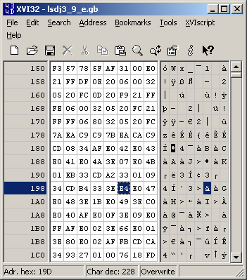
BGB stops and show a bunch of machine instructions. The interesting part is the instructions at 019C and 019E. The instruction at 019C takes the hexadecimal value $E4, stores it in the CPU register A then writes it to the hardware register $FF47. This is the code we’re looking for. The value $E4 is the standard palette. Go back to pan docs and check again how the value is constructed.
Then let’s split the value into its individual colours.
$E4 = 11 10 01 00
11 is the lightest palette value and 00 is the darkest. Since want to invert the palette we’ll reverse the order.
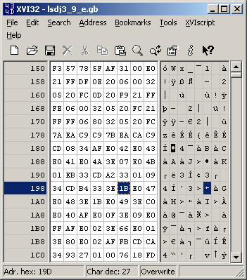
00 01 10 11 = $1B
Great. You may now right click the line at 019C, choose modify code and enter ld a,1B. The line that said ld a,E4 should now say ld a,1B. Choose run, reset to confirm that the palette is inverted and that LSDj doesn’t crash or anything. You may now go to file, save ROM as and save the file anywhere you want, preferably with a new file name.
Alternatively, you can use a hex editor to edit this value. This part of the tutorial was left unchanged from the first version, because no$gmb can’t save changes made to a ROM and thus needed a hex editor to modify the file.
Open the hex editor and replace the $E4 at position 019D with the value $1B. This address will vary depending on LSDj version.
Lastly, open the ROM in an emulator to confirm that the modification worked.
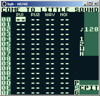
Enjoy the inverted palette.
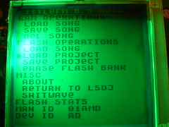
Green Gameboy backlight
December 6th, 2009(Most photos have Flickr notes. If you click on any of the pictures, you’ll go to that photo’s Flickr page where you can watch notes for the photos that have them.)
I’ve playing around a lot with DMG backlight lately. After I tried out the inversion hack on my guinea pig boy, I installed the hack on my regular one as well, but without a switch, and flipped the polarization layer of course. (The whole point of the hack is to uninvert the screen after flipping the polarization layer) This gave it more contrast, but then Bibin gave me a tip that so called “kelly green” coloured LEDs would work perfectly for a DMG backlight when using the inverse polarization layout, since the dark areas would completely block that green wavelength, whereas a large portion of white light will pass through even the dark areas. I believe that “kelly green” is the same LED type as “true green”. The LEDs in this eBay auction are suitable for the job, if you want to build your own backlight using this method.
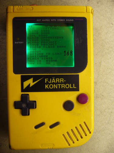
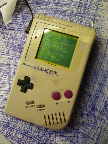
Compare the images below:
The left picture is a Nonfinite backlight with an inverted polarizer. (And of course a 74hc04 screen inverter to uninvert the image) It has white LEDs which is atcually a bad idea for use with a monochrome LCD. Light pixels will conduct all wavelengths of light pretty evenly. Dark pixels on the other hand block green light but will still pass through a considerable amount of blue light. Add to that the white LEDs commonly used are actually blue LEDs with phosphor to produce other wavelengths. Read about it on Wikipedia. Because of this, white LEDs will have a much higher concentration of blue light compared to other wavelengths, which doesn’t exactly help getting contrast and gives the dark areas this purple colour. When using the green LED on the other hand, you only get one wavelength of light, which is almost perfectly blocked by dark pixels, giving you great contrast.
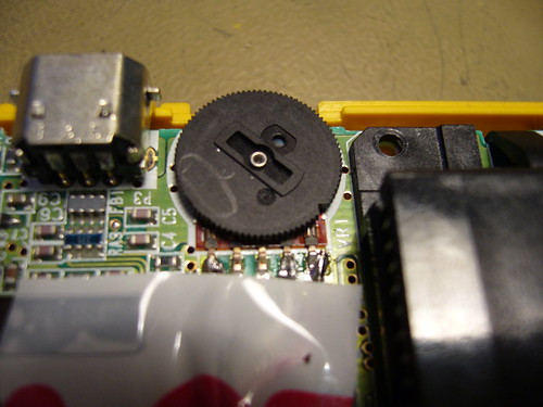
LED circuit board
For this chapter of my epic eternal backlight saga I used three LEDs from a batch I recently acquired, combined with layers from a backlight taken from a broken laptop screen. The LEDs are surface mount 45° wide angle
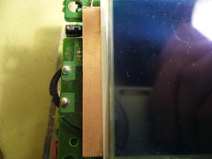

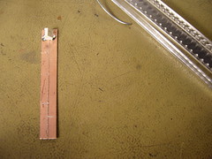
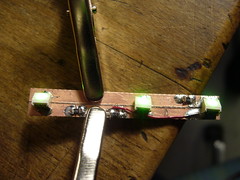
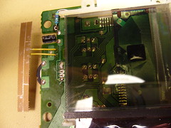
I needed a circuit board to keep the LEDs in place. It seemed like a waste to make a printed board a one-off piece of such a simple board, so I simply cut the needed traces and soldered components onto a copper laminate. I connected it to the screen daughterboard with a relatively thick single strand wire which also keeps the board in position.
The layers
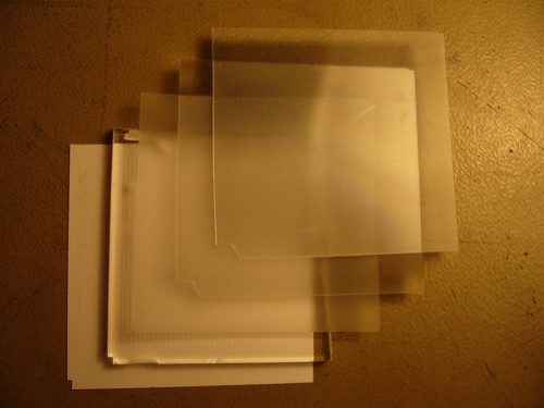
And so a word about the layers used behind the screen… Lightboy made a thread on 8bc describing his backlight method. When seeing his desciption of the layers I was unsure what the layers were, but now that I have a complete backlight unit from a computer screen I have investigated the layers, so here’s an explanation of what the different layers are.
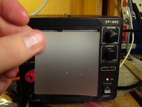
The bottom layer, not pictured, is the reflection layer. In this screen it was blank white plastic, as opposed to a silver colored mirror. The next layer, as pictured above, is the diffusion layer. Its job is to lead the light from the light source at the side and distribute it evenly upwards. It does so by small bumps in the bottom of the layer. The world has seen better Dremel jobs, but I suppose it works. This layer is also a couple millimeters thick, which created problems, see the bottom of the post.
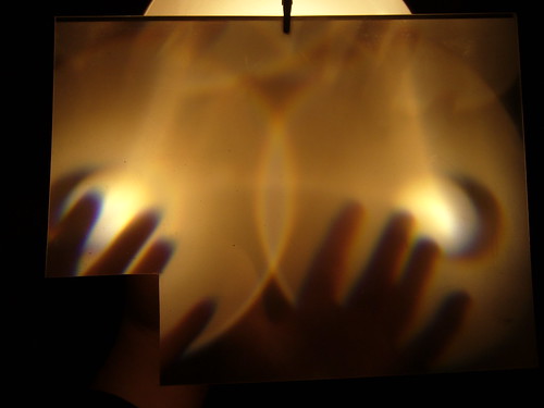
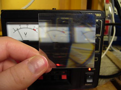
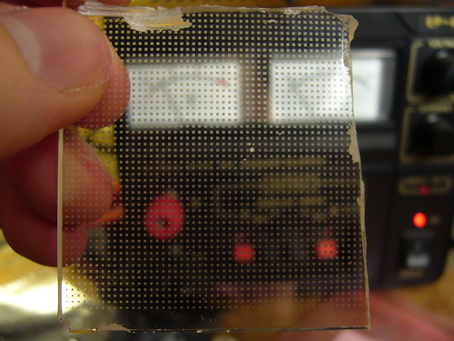
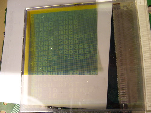
The top picture may look like something straight out of The Twilight Zone, but it’s in fact my favorite layer of the five, the growth foil. What it does, as far as I can tell, is to collect light from two directions and send it up. There are two versions of this layer stacked, one that collects light vertically and one thta collects light horizontally. The top picture is me holding one hand in front of a lamp, which the layer duplicates because it collects light from two directions. I ought to cut of pieces of those layers and make trippy sunglasses out of them.
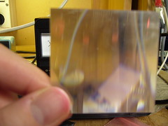
The blur foil is simply a foil of “brushed” plastic to even out the light distribution.
The topmost layer is the polarizing layer. To understand what this layer does you need to understand what polarization is and how it works. Read about it on nobelprize.org.
The final result
I’m not really satisfied with the outcome. This backlight has a flaw… The diffusion layer is too thick, which creates pressure on the LCD and creates differences in contrast in the areas that are under stress. And the layers are unaligned, creating a dark gap in the top of the screen. I can fix all those things however, and when that’s done I think this is the backlight design I’ll finally stick with.
I will also try to see if I can replace the white LEDs in my Nonfinite backlight panel, to use the green ones I have now.
How to patch your DMG to use a biverted palette
November 23rd, 2009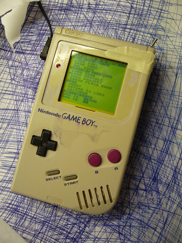
Inverted:
(Please excuse the shabby look, but that is my guinea pig Gameboy that I use for experimentation.)
I’ve already explained how you can invert the monochrome palette in LSDj which is useful if you have a DMG backlight with an inverted polarizer film on your DMG. But what if you want to use a normal palette for other software or games?
Modding the ROM of the game or program you want to invert the palette for is an option, but it may not be practical. Fear not however, the protocol that the DMG is using to transfer data from its all-in-one chip to the LCD is strikingly simple, and can easily be inverted with a 74hc logic circuit of your choice, a so-called biversion.
First let’s have a look at how the protocol works.
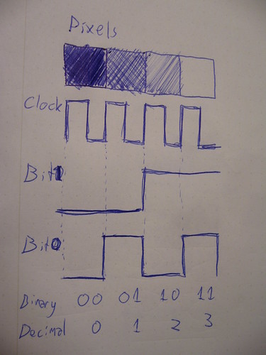
For the sake of this tutorial there are three important pins to keep track of. Data bit 0, data bit 1 and clock. At every rising edge clock edge (when the clock line changes from 0V to +5V) the current state of the data lines is recorded, and the corresponding pixel value is drawn to the currently active pixel on the LCD. This keeps goes until the whole screen is filled with an image. And then again and again. (Ok, there are more aspects to it, like so called “blanking” but that’s not relevant for this discussion)
So what you need to do is change the values of the data lines in such a way that black becomes white, light gray becomes dark gray and so on. The way to do this is by simply inverting the two data bits. There are (at least) two possible ways to do this.
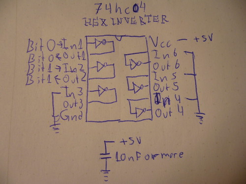
One way is to use a simple inverter like 74hc04, where you connect the data bits to the appropriate input and outputs. Also note two things abut the schematic:
1) I have connected all unused input to ground. (Unused outputs should remain unconnected)
2) I’ve added a bypass capacitor between Gnd and +5V
Neither one of these things are strictly necessary but they are good practice, and may help reduce interference to the signal if that would be a problem.
And obviously you can use any pair of inputs and outputs on the chip.
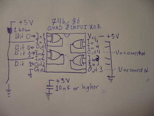
The other way of doing it, which is what I did for my prototype, is to use xor gates. (74hc86) The advantage of that method is that you can switch between the modes easily with a switch. If you xor a bit value with 0, you get back the same bit value. If you instead xor the bit value with 1, you get back the inverted value. So in this configuration, I’ve connected a weak pullup resistor, which sets one of the inputs to 1 by default, meaning the image is inverted by default. However, if those inputs are shorted to ground, the xor operation returns the original data and the picture is again unaffected.
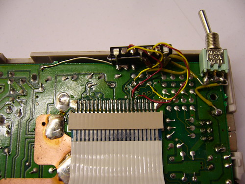
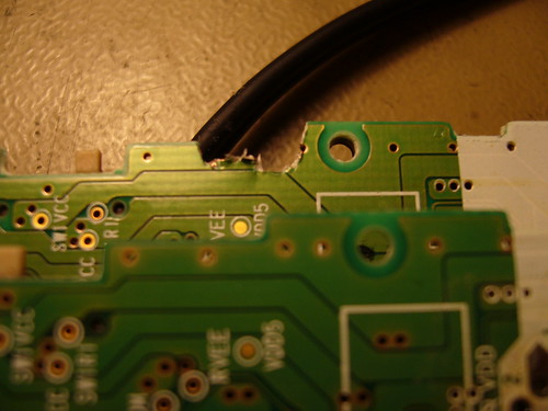
So, how does one actually connect the inverter? You need to cut the copper trace where the data and solder the input and outputs on each side of the cut.
This is what my prototype circuit looks like. I’ve connected the inputs of the inverter to the appropriate holes that are already available in the motherboard, but filled with solder.
A sidenote on these holes: They were most probably placed there to enable connection to the WideBoy unit, which was an official Nintendo development kit that allowed the screen image of a Gameboy to be displayed on a TV with the help of a NES.
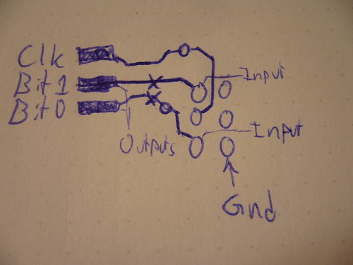
At any rate they come in handy now. The above diagram show you where to tap the input signals, where to cut the traces, and where to solder the output wires. When cutting the traces make sure you cut them properly, or you’ll have a conflict. Do not cut the Clk trace.
All three holes shown to the right in the diagram are connected to Gnd.
Last but not least, a video of the thing in action:
So… Tell me what you think. Is this information useful? Anything unclear? Is my English to quirky and corny? Anyone interested in buying kits for this thing?
The terms “biversion” and “bivert” were later coined for this mod by Bibin.
Pictures of inverted palette LSDj running on an inverted DMG screen
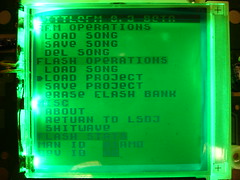
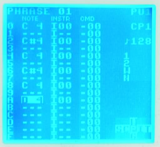
November 2nd, 2009Blue standard polarity (?) DMG screen running LSDj with an inverted palette
Red inverse polarity DMG screen running LSDj with an inverted palette
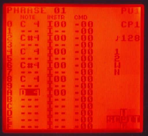
Thanks 30003019 for the pictures. He comments “anyway, it makes the inverted red backlight a lot less painful to the eyes”.
Gijs’ Gameboy Camera Animation Converter
September 17th, 2009
GB Camera Sav -> GIF animation converter by Gijs Gieskes
mGB with extended MIDI channel support
September 16th, 2009 I’ve had the privilege of getting access to trash80’s mGB code, which of course has given me the opportunity to make improvements. My first improvement is to add support for extended MIDI channels. (1-5,6-10 or 11-15 depending on which ROM you’re using.) This is useful for people who want to use mGB on the same MIDI output as MIDINES, other synths or perhaps use 3 copies of mGB simultaneously with one Arduinoboy. (With three link cable plugs).
In a future hacked version I’ll include the ability to choose which channels to use in the program, and also make mGB play nicer with LSDj. (Not corrupting savs and so on)
GBC Prosound idea
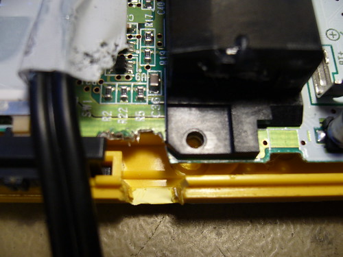
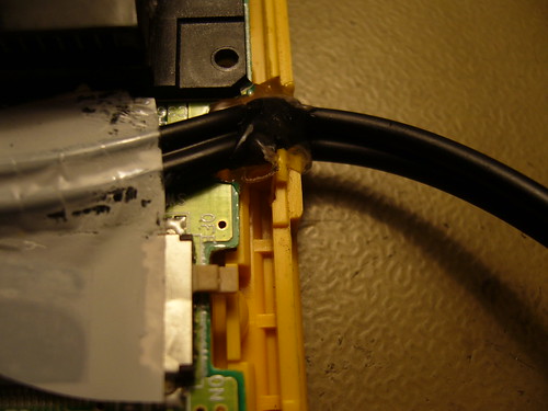
September 13th, 2009Sorry for the blog hiatus during and after my vacation. Before the vacation I came up with a new way of routing the audio cable that I don’t think I’ve seen before. (Feel free to correct me.) Most GBC prosound mods I’ve seen are based in the idea of routing the cable downwards to the bottom of the board.
My idea on the other hand is based on connecting the audio wires to the potentiometer as usual, then routing the cable over the PCB, so that it sits below the cartridge when the GBC is reassembled. The cable would then exit through a hole on the right side of the of unit.
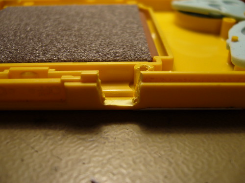
The trick however, to make this mod work, is to cut away a piece of the PCB to make room for the cable. The copper trace that is affected, is relatively wide, so there’s some margin. However, it’s for the power supply, so there’s a small risk that you might need to compensate for the loss in size be adding an extra wire. I haven’t had any problems with this yet, but I guess this would depend on how big a piece of the board you cut away. The only slight problem I had was that the cable just barely fit into the space when reassembling the GBC. But it seems to adjusted itself and it now works beautifully.
Pics:
The wires soldered to the potentiometer. I soldered the wires pre-pot to always get maximum volume and minimum impedance. (I’ll always be connecting it to a mixer anyway.)
The notch in the PCB (Front) - modded vs unmodded board
The notch in the PCB (back)
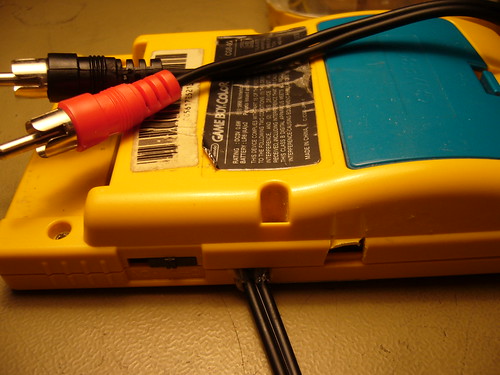
The hole where the cable exits
Zoomed out

Some hot glue to fix the cable
The final product (Reassembled)
What thinks?
Testing Gameboy input voltage ranges
July 22nd, 2009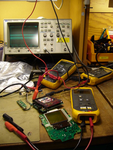
Introduction
Recently there was a discussion about on 8bc about a new way of backlighting DMG’s. Bonewire’s backlighting method replaces the batteries with two 9V batteries. This raised the discussion of whether you could power the Gameboy directly with a 9V battery, or whether it would explode/otherwise fail.
I wrote a post about the inner workings of the regulator and promised to come back with some more measurements of the performance of the regulator at different voltage levels.
To clear possible confusion: One important aspect of the regulator is that it’s a switching type regulator which is using a feedback mechanism to keep the voltage steady. Because of its design it’s able to do so whether the input voltage is lower or higher than the target voltage of about +5V. Thus, the input voltage may vary, while the output voltage stays (relatively) constant. This is useful for battery operation since the batteries can used as long as they are able to give enough current, whether or not their voltage is low. Switching power regulators, in general, also have a power conversion ratio: Little energy is lost in the conversion. (As opposed to a linear regulator, like the 7805 & co, which are guranteed to wate at least a certain amount of energy as heat)
Test Conditions
The goal of the test is to benchmark the input voltage range at which a Gameboy power supply would work at. The test subject was a DMG-CPU-7 revision motherboard with a DC CONV DMG converter. (There are at least two versions of the regulator board; the other one is marked DC CONV 2 DMG and has a couple more components on it.)
I used a xzakox type flash cartridge loaded with LSDj, playing a melody, with power save set to off.
Here a few notes on the measured values:
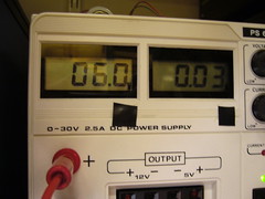
- Vin was adjusted in steps of 0.5 V and 1.0 V. The value is accurate to ±10 mV for all it matters
- Vout was measured with a multimeter and is accurate.
- Iin is the input current as displayed by the power supply unit, and is fairly inaccurate. (It only shows the general tendency)
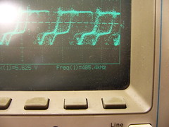
- DC/DC control RMS/f This value is also a bit hit and miss. I tried to read out the frequency which the DC/DC converter was working at, from the oscilloscope, to the best of my ability. This value fluctuated a lot, and is also just there to give a general picture of the freqeuncy. At the lower values the oscilloscope was unable to detect the frequency at all.
That is what the cryptic RMS voltage is there for. It should give a rough idea of the duty cycle of the control wave. - Notes These are my observations for some of the voltages.
Test Data
| Vin (V) | IIn (A) | Vout (V) | DC/DC control RMS/f | Notes |
| 1.5 | 0.15 | 4.79 | ~2.1V | Prone to crash, no sound, DC/DC buzz on startup |
| 2.0 | 0.12 | 4.82 | ~2.4V | No sound |
| 2.5 | 0.11 | 4.84 | ~2.7V | Display will lose data when playing sound |
| 3.0 | 0.05 | 4.87 | ~3.0V/~260kHz | Appears to work normally, possibly a bit glitchy/unstable |
| 3.5 | 0.06 | 4.86 | ~3.2V | |
| 4.0 | 0.05 | 4.87 | ~3.5V/~300kHz | Fully normal operation |
| 5.0 | 0.05 | 4.88 | ~3.5V/~320kHz | |
| 6.0 | 0.04 | 4.89 | ~3.6V/~390kHz | |
| 7.0 | 0.04 | 4.89 | ~3.6V/~415kHz | |
| 8.0 | 0.04 | 4.90 | ~3.6V/~460kHz | |
| 9.0 | 0.03 | 4.90 | ~3.7V/~500kHz | |
| 10.0 | 0.03 | 4.90 | ~3.7V/~510kHz | |
| 11.0 | 0.03 | 4.89 | ~3.0V/~700kHz?? | |
| 12.0 | 0.03 | 4.89 | ~2.6V/??? |
Observations and conclusions
Low voltage operation
The first interesting observation is the behavior in the low end of the voltage spectrum. The regulator could manage to keep the CPU alive at an input voltage as low as 1.5V. However, at that voltage there were significant power losses in the conversion, sound wouldn’t work and the Gameboy would crash easily.
At the transition 2.5V->3V you can see a significant change in input current, and I also noticed a change in behavior on the oscilloscope. I’d define 3V as the absolute minimum voltage that the regulator board can handle stable.
Sidenote: This possibly opens the door for using a Li-Ion battery for powering a DMG.
Normal voltage operation
At 4.0 V the Gameboy is definitely operating normally. As the input voltage is increased, the switching frequency is increased of the regulator is increased. No abnormal behavior. At no point during the testing did I notice and excessive heat production in the regulator circuit.
Above-normal voltage operation
4 AA batteries can not reasonably produce voltages higher than 7 V, so anything above that could be seen as outside the standard range of operation.
So what are the effects of voltages above 7 V? The regulator itself seems to handle it fairly well. And the +5V output only fluctuates 100 mV, so the CPU won’t be affected. However, while the +5V is regulated, the -18V line used by the LCD is not directly regulated, but instead current limited by a 510 Ohm resistor.
It is possible that the increased input voltage will also increase the LCD voltage in such a way that it damages the LCD. The Gameboy I used for testing already had a slightly damaged display, but when I was done wih the testing its display was more or less completely broken (would turn off or glitch out within seconds after turning on the power, regardless of input voltage)
I tried feeding my known good Gameboy with 9V for a few minutes, with a moderate contrast setting, without any problems. However, it’s possible that the extreme positions of the contrast dial will slowly destroy the LCD, when the input voltage is >7 V. If so, it could probably be fixed by changing the control voltage range for the contrast dial.
I’ll have to investigate that further, but my preliminary conclusion is that you can feed the Gameboy with a 9V battery without problems.
Arduinoboy for Arduino Pro Mini 5V (PCB giveaway!)
July 5th, 2009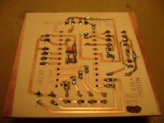
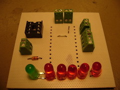
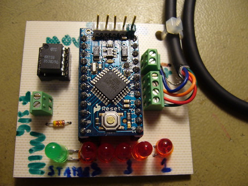
So this is my version of an Arduinoboy board which, unlike other designs (?) is using an Arduino Pro Mini as the base, SMD resistors and capacitors instead of hole mount ones and is using screw terminal blocks for external connectors.
I’ll share the design of it as soon as I’ve straightened out a couple of small design errors. The two-terminal blocks have small pins that are supposed to go through a hole in the PCB for added stability. I drilled these extra holes even though some of them destroyed copper leads. (That’s what the patch leads are for in the upper left picture) The LED’s are also a bit to close to each other.
I’ll redesign the board and etch a new board with the fixes. But I’ve already etched two boards with the old layout, and I was going to trash one of them, but if anyone is interested, I can send it to you at the cost of the shipping. The board is equipped with as shown in the upper pictures. I’ll also add the pin headers needed to connect the Arduino to the board. I can also attach (relatively low-intensity) LEDs. NO peripherals are included, so you’ll need an Arduino Pro Mini 5V, 6N138, a link cable, power supply (Unless you did the Taco-04 Taco swap mod), MIDI jack and a button if you want that functionality.
If you’re interested, leave a comment or mail me (My e-mail address should be visible below)
TI-boy SE - A Game Boy emulator for TI calculators
June 28th, 2009 About 7 years ago people discussed whether the then new Game Boy Advance could emulate SNES games. The general reponse was that the GBA would be able to emulate SNES when hell froze over. So came SNES Advance by Loopy and Flubba, and hell froze over. Sure it was slow and didn’t have sound, but it was proof of concept that it could be done.
People said the same thing about Game Boy emulation on the TI-8x series of calculators. Yet, calc84/calc84maniac recently released the first public beta version of his TI-boy SE emulator. And it even has sound. ![]()
The emulator works on some TI-8x calculators (TI-83+SE, TI-84+, and TI-84+SE) and has support for a small number of games, for example Tetris, Zelda - Link’s Awakening and Kirby. Even if it’s slow, and sometimes glitchy it’s an amazing feat. I would definitely dub this the coolest TI calculator project of this year. (Or perhaps ever…)
The emulator works by using the similarity between the Z80 and the Game Boy CPU (which is a reduced and slightly modified Z80) in a clever way. I’ll write more about the details in a future post.
Links:
Download from ticalc.org
Download from gbdev.gg8.se (Mirror, v0.0.2 alpha)
Discussion on the Omnimaga forums
Youtube video (With sound)
Youtube video (Grayscale)
This post on gbdev.gg8.se